


This package contains basic analog electrical components:
Modelica.Electrical.Analog.Basic.Ground

Ground of an electrical circuit. The potential at the ground node is zero. Every electrical circuit has to contain at least one ground object.
model Ground "Ground node"
  Interfaces.Pin p;
equation
  p.v = 0;
end Ground;
Modelica.Electrical.Analog.Basic.Resistor
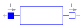
The linear resistor connects the branch voltage v with the branch current i by i*R = v. The Resistance R is allowed to be positive, zero, or negative.
| Name | Default | Description |
|---|---|---|
| R | 1 | Resistance [Ohm] |
model Resistor "Ideal linear electrical resistor"
  extends Interfaces.OnePort;
  parameter SI.Resistance R=1 "Resistance";
equation
  R*i = v;
end Resistor;
Modelica.Electrical.Analog.Basic.HeatingResistor
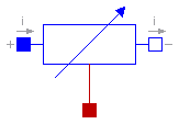
This is a model for an electrical resistor where the generated heat is dissipated to the environment via connector heatPort and where the resistance R is temperature dependent according to the following equation:
R = R_ref*(1 + alpha*(heatPort.T - T_ref))
alpha is the temperature coefficient of resistance, which is often abbreviated as TCR. In resistor catalogues, it is usually defined as X [ppm/K] (parts per million, similarly to per centage) meaning X*1.e-6 [1/K]. Resistors are available for 1 .. 7000 ppm/K, i.e., alpha = 1e-6 .. 7e-3 1/K;
When connector heatPort is not connected, the temperature dependent behaviour is switched off by setting heatPort.T = T_ref. Additionally, the equation heatPort.Q_dot = 0 is implicitly present due to a special rule in Modelica that flow variables of not connected connectors are set to zero.
| Name | Default | Description |
|---|---|---|
| R_ref | Resistance at temperature T_ref [Ohm] | |
| T_ref | 300 | Reference temperature [K] |
| alpha | 0 | Temperature coefficient of resistance [1/K] |
model HeatingResistor "Temperature dependent electrical resistor"
  extends Interfaces.OnePort;

  parameter SI.Resistance R_ref "Resistance at temperature T_ref";
  parameter SI.Temperature T_ref=300 "Reference temperature";
  parameter Real alpha(unit="1/K") = 0 "Temperature coefficient of resistance";

  SI.Resistance R "Resistance = R_ref*(1 + alpha*(heatPort.T - T_ref));";

  Modelica.Thermal.HeatTransfer.Interfaces.HeatPort_a heatPort;
equation
  v = R*i;

  if cardinality(heatPort) > 0 then
    R = R_ref*(1 + alpha*(heatPort.T - T_ref));
    heatPort.Q_dot = -v*i;
  else
    /* heatPort is not connected resulting in the
         implicit equation 'heatPort.Q_dot = 0'
      */
    R = R_ref;
    heatPort.T = T_ref;
  end if;
end HeatingResistor;
Modelica.Electrical.Analog.Basic.Conductor
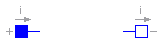
The linear conductor connects the branch voltage v with the branch current i by i = v*G. The Conductance G is allowed to be positive, zero, or negative.
| Name | Default | Description |
|---|---|---|
| G | 1 | Conductance [S] |
model Conductor "Ideal linear electrical conductor"
  extends Interfaces.OnePort;
  parameter SI.Conductance G=1 "Conductance";
equation
  i = G*v;
end Conductor;
Modelica.Electrical.Analog.Basic.Capacitor
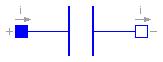
The linear capacitor connects the branch voltage v with the branch current i by i = C * dv/dt. The Capacitance C is allowed to be positive, zero, or negative.
| Name | Default | Description |
|---|---|---|
| C | 1 | Capacitance [F] |
model Capacitor "Ideal linear electrical capacitor"
  extends Interfaces.OnePort;
  parameter SI.Capacitance C=1 "Capacitance";
equation
  i = C*der(v);
end Capacitor;
Modelica.Electrical.Analog.Basic.Inductor
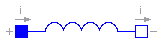
The linear inductor connects the branch voltage v with the branch current i by v = L * di/dt. The Inductance L is allowed to be positive, zero, or negative.
| Name | Default | Description |
|---|---|---|
| L | 1 | Inductance [H] |
model Inductor "Ideal linear electrical inductor"
  extends Interfaces.OnePort;
  parameter SI.Inductance L=1 "Inductance";
equation
  L*der(i) = v;
end Inductor;
Modelica.Electrical.Analog.Basic.Transformer
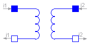
The transformer is a two port. The left port voltage v1, left port current i1, right port voltage v2 and right port current i2 are connected by the following relation:
         | v1 |         | L1   M  |  | i1' |
         |    |    =    |         |  |     |
         | v2 |         | M    L2 |  | i2' |
L1, L2, and M are the primary, secondary, and coupling inductances respectively.
| Name | Default | Description |
|---|---|---|
| L1 | 1 | Primary inductance [H] |
| L2 | 1 | Secondary inductance [H] |
| M | 1 | Coupling inductance [H] |
model Transformer "Transformer with two ports"
  extends Interfaces.TwoPort;
  parameter SI.Inductance L1=1 "Primary inductance";
  parameter SI.Inductance L2=1 "Secondary inductance";
  parameter SI.Inductance M=1 "Coupling inductance";
equation
  v1 = L1*der(i1) + M*der(i2);
  v2 = M*der(i1) + L2*der(i2);
end Transformer;
Modelica.Electrical.Analog.Basic.Gyrator
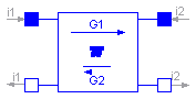
A gyrator is a two-port element defined by the following equations:
    i1 =  G2 * v2
    i2 = -G1 * v1
where the constants G1, G2 are called the gyration conductance.
| Name | Default | Description |
|---|---|---|
| G1 | 1 | Gyration conductance [S] |
| G2 | 1 | Gyration conductance [S] |
model Gyrator "Gyrator"
  extends Interfaces.TwoPort;
  parameter SI.Conductance G1=1 "Gyration conductance";
  parameter SI.Conductance G2=1 "Gyration conductance";
equation
  i1 = G2*v2;
  i2 = -G1*v1;
end Gyrator;
Modelica.Electrical.Analog.Basic.EMF
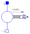
EMF transforms electrical energy into rotational mechanical energy. It is used as basic building block of an electrical motor. The mechanical connector flange_b can be connected to elements of the Modelica.Mechanics.Rotational library. flange_b.tau is the cut-torque, flange_b.phi is the angle at the rotational connection.
| Name | Default | Description |
|---|---|---|
| k | 1 | Transformation coefficient [N.m/A] |
model EMF "Electromotoric force (electric/mechanic transformer)"
  parameter Real k(final unit="N.m/A") = 1 "Transformation coefficient";

  SI.Voltage v "Voltage drop between the two pins";
  SI.Current i "Current flowing from positive to negative pin";
  SI.AngularVelocity w "Angular velocity of flange_b";
  Interfaces.PositivePin p;
  Interfaces.NegativePin n;
  Modelica.Mechanics.Rotational.Interfaces.Flange_b flange_b;
equation
  v = p.v - n.v;
  0 = p.i + n.i;
  i = p.i;

  w = der(flange_b.phi);
  k*w = v;
  flange_b.tau = -k*i;
end EMF;
Modelica.Electrical.Analog.Basic.VCV
The linear voltage-controlled voltage source is a TwoPort. The right port voltage v2 is controlled by the left port voltage v1 via
v2 = v1 * gain.
The left port current is zero. Any voltage gain can be chosen.
| Name | Default | Description |
|---|---|---|
| gain | 1 | Voltage gain |
model VCV "Linear voltage-controlled voltage source"
  extends Interfaces.TwoPort;
  parameter Real gain=1 "Voltage gain";
equation
  v2 = v1*gain;
  i1 = 0;
end VCV;
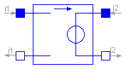
Modelica.Electrical.Analog.Basic.VCC
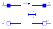
The linear voltage-controlled current source is a TwoPort. The right port current i2 is controlled by the left port voltage v1 via
i2 = v1 * transConductance.
The left port current is zero. Any transConductance can be chosen.
| Name | Default | Description |
|---|---|---|
| transConductance | 1 | Transconductance [S] |
model VCC "Linear voltage-controlled current source"
  extends Interfaces.TwoPort;
  parameter SI.Conductance transConductance=1 "Transconductance";
equation
  i2 = v1*transConductance;
  i1 = 0;
end VCC;
Modelica.Electrical.Analog.Basic.CCV
The linear current-controlled voltage source is a TwoPort. The right port voltage v2 is controlled by the left port current i1 via
v2 = i1 * transResistance.
The left port voltage is zero. Any transResistance can be chosen.
| Name | Default | Description |
|---|---|---|
| transResistance | 1 | Transresistance [Ohm] |
model CCV "Linear current-controlled voltage source"
  extends Interfaces.TwoPort;

  parameter SI.Resistance transResistance=1 "Transresistance";
equation
  v2 = i1*transResistance;
  v1 = 0;
end CCV;
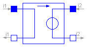
Modelica.Electrical.Analog.Basic.CCC
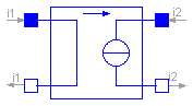
The linear current-controlled current source is a TwoPort. The right port current i2 is controlled by the left port current i1 via
i2 = i1 * gain.
The left port voltage is zero. Any current gain can be chosen.
| Name | Default | Description |
|---|---|---|
| gain | 1 | Current gain |
model CCC "Linear current-controlled current source"
  extends Interfaces.TwoPort;
  parameter Real gain=1 "Current gain";
equation
  i2 = i1*gain;
  v1 = 0;
end CCC;
Modelica.Electrical.Analog.Basic.OpAmp
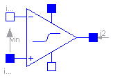
The OpAmp is a simle nonideal model with a smooth out.v = f(vin) characteristic, where "vin = in_p.v - in_n.v". The characteristic is limited by VMax.v and VMin.v. Its slope at vin=0 is the parameter Slope, which must be positive. (Therefore, the absolute value of Slope is taken into calculation.)
| Name | Default | Description |
|---|---|---|
| Slope | 1 | Slope of the out.v/vin characteristic at vin=0 |
model OpAmp "Simple nonideal model of an OpAmp with limitation"
  parameter Real Slope=1 "Slope of the out.v/vin characteristic at vin=0";
  Modelica.Electrical.Analog.Interfaces.PositivePin in_p
    "Positive pin of the input port";
  Modelica.Electrical.Analog.Interfaces.NegativePin in_n
    "Negative pin of the input port";
  Modelica.Electrical.Analog.Interfaces.PositivePin out "Output pin";
  Modelica.Electrical.Analog.Interfaces.PositivePin VMax
    "Positive output voltage limitation";
  Modelica.Electrical.Analog.Interfaces.NegativePin VMin
    "Negative output voltage limitation";
  SI.Voltage vin "input voltagae";
protected
  Real f "auxiliary variable";
  Real absSlope;
equation
  in_p.i = 0;
  in_n.i = 0;
  VMax.i = 0;
  VMin.i = 0;
  vin = in_p.v - in_n.v;
  f = 2/(VMax.v - VMin.v);
  absSlope = if (Slope < 0) then -Slope else Slope;
  out.v = (VMax.v + VMin.v)/2 + absSlope*vin/(1 + absSlope*noEvent(if (f*vin <
    0) then -f*vin else f*vin));
end OpAmp;