 Modelica.Electrical.Analog.Interfaces.Pin


This package contains connectors and interfaces (partial models) for analog electrical components.
 Modelica.Electrical.Analog.Interfaces.Pin

connector Pin "Pin of an electrical component"
  SI.Voltage v "Potential at the pin";
  flow SI.Current i "Current flowing into the pin";
end Pin;
 Modelica.Electrical.Analog.Interfaces.OnePort

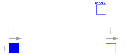
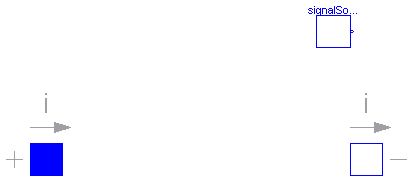
Superclass of elements which have two electrical pins: the positive pin connector p, and the negative pin connector n. It is assumed that the current flowing into pin p is identical to the current flowing out of pin n. This current is provided explicitly as current i.
partial model OnePort
  "Component with two electrical pins p and n and current i from p to n"

  SI.Voltage v "Voltage drop between the two pins (= p.v - n.v)";
  SI.Current i "Current flowing from pin p to pin n";
  PositivePin p;
  NegativePin n;
equation
  v = p.v - n.v;
  0 = p.i + n.i;
  i = p.i;
end OnePort;
 Modelica.Electrical.Analog.Interfaces.TwoPort

partial model TwoPort
  "Component with two electrical ports, including current"
  SI.Voltage v1 "Voltage drop over the left port";
  SI.Voltage v2 "Voltage drop over the right port";
  SI.Current i1 "Current flowing from pos. to neg. pin of the left port";
  SI.Current i2 "Current flowing from pos. to neg. pin of the right port";
  PositivePin p1 "Positive pin of the left port";
  NegativePin n1 "Negative pin of the left port";
  PositivePin p2 "Positive pin of the right port";
  NegativePin n2 "Negative pin of the right port";
equation
  v1 = p1.v - n1.v;
  v2 = p2.v - n2.v;
  0 = p1.i + n1.i;
  0 = p2.i + n2.i;
  i1 = p1.i;
  i2 = p2.i;
end TwoPort;
 Modelica.Electrical.Analog.Interfaces.PositivePin

Connectors PositivePin and NegativePin are nearly identical. The only difference is that the icons are different in order to identify more easily the pins of a component. Usually, connector PositivePin is used for the positive and connector NegativePin for the negative pin of an electrical component.
connector PositivePin "Positive pin of an electric component"
  SI.Voltage v "Potential at the pin";
  flow SI.Current i "Current flowing into the pin";
end PositivePin;
 Modelica.Electrical.Analog.Interfaces.NegativePin

Connectors PositivePin and NegativePin are nearly identical. The only difference is that the icons are different in order to identify more easily the pins of a component. Usually, connector PositivePin is used for the positive and connector NegativePin for the negative pin of an electrical component.
connector NegativePin "Negative pin of an electric component"
  SI.Voltage v "Potential at the pin";
  flow SI.Current i "Current flowing into the pin";
end NegativePin;
 Modelica.Electrical.Analog.Interfaces.TwoPin

partial model TwoPin "Component with one electrical port"
  SI.Voltage v "Voltage drop between the two pins (= p.v - n.v)";
  PositivePin p "Positive pin";
  NegativePin n "Negative pin";
equation
  v = p.v - n.v;
end TwoPin;
 Modelica.Electrical.Analog.Interfaces.AbsoluteSensor

partial model AbsoluteSensor
  "Base class to measure the absolute value of a pin variable"
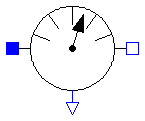
  extends Modelica.Icons.RotationalSensor;

  PositivePin p "pin to be measured";
  Modelica.Blocks.Interfaces.OutPort outPort(final n=1);
end AbsoluteSensor;
 Modelica.Electrical.Analog.Interfaces.RelativeSensor

partial model RelativeSensor
  "Base class to measure a relative variable between two pins"
  extends Modelica.Icons.RotationalSensor;

  PositivePin p "positive pin";
  NegativePin n "negative pin";
  Modelica.Blocks.Interfaces.OutPort outPort(final n=1);


end RelativeSensor;
 Modelica.Electrical.Analog.Interfaces.VoltageSource

| Name | Default | Description |
|---|---|---|
| offset | 0 | Voltage offset [V] |
| startTime | 0 | Time offset [s] |
| signalSource |
partial model VoltageSource "Interface for voltage sources"
  extends OnePort;

  parameter SI.Voltage offset=0 "Voltage offset";
  parameter SI.Time startTime=0 "Time offset";
  replaceable Modelica.Blocks.Interfaces.SignalSource signalSource(final offset={offset}
      , final startTime={startTime});
equation
  v = signalSource.outPort.signal[1];
end VoltageSource;
 Modelica.Electrical.Analog.Interfaces.CurrentSource

| Name | Default | Description |
|---|---|---|
| offset | 0 | Current offset [A] |
| startTime | 0 | Time offset [s] |
| signalSource |
partial model CurrentSource "Interface for current sources"
  extends OnePort;

  parameter SI.Current offset=0 "Current offset";
  parameter SI.Time startTime=0 "Time offset";
  replaceable Modelica.Blocks.Interfaces.SignalSource signalSource(final offset={offset}
      , final startTime={startTime});
equation
  i = signalSource.outPort.signal[1];
end CurrentSource;