


This package contains connectors and partial models for 1D rotational mechanical components. In particular
  Flange_a         Left flange of a component.
  Flange_b         Right flange of a component.
  Rigid            Rigid connection of two rotational 1D flanges
                   (used for elements with inertia).
  Compliant        Compliant connection of two rotational 1D flanges
                   (used for force laws such as a spring or a damper).
  TwoFlanges       Component with two rotational 1D flanges
  AbsoluteSensor   Base class to measure absolute flange variables.
  Relative Sensor  Base class to measure relative flange variables.
Release Notes:
Copyright © 1999-2002, Modelica Association and DLR.
The Modelica package is free software; it can be redistributed and/or modified under the terms of the Modelica license, see the license conditions and the accompanying disclaimer in the documentation of package Modelica in file "Modelica/package.mo".
Modelica.Mechanics.Rotational.Interfaces.Rigid

This is a 1D rotational component with two rigidly connected flanges, i.e., flange_a.phi = flange_b.phi. It is used e.g. to built up components with inertia.
Release Notes:
partial model Rigid
  "Base class for the rigid connection of two rotational 1D flanges"

  SI.Angle phi
    "Absolute rotation angle of component (= flange_a.phi = flange_b.phi)";

  Flange_a flange_a
    "(left) driving flange (flange axis directed INTO cut plane)";
  Flange_b flange_b
    "(right) driven flange (flange axis directed OUT OF cut plane)";
equation
  flange_a.phi = phi;
  flange_b.phi = phi;
end Rigid;
Modelica.Mechanics.Rotational.Interfaces.TwoFlanges

This is a 1D rotational component with two flanges. It is used e.g. to built up parts of a drive train consisting of several base components. There are specialized versions of this base class for rigidly connected flanges (Interfaces.Rigid) and for a compliant connection of flanges (Interfaces.Compliant).
Release Notes:
partial model TwoFlanges
  "Base class for a component with two rotational 1D flanges"
  Flange_a flange_a;
  Flange_b flange_b;
end TwoFlanges;
Modelica.Mechanics.Rotational.Interfaces.Flange_a

This is a connector for 1D rotational mechanical systems and models a mechanical flange. The following variables are defined in this connector:
   phi: Absolute rotation angle of the flange in [rad].
   tau: Cut-torque in the flange in [Nm].
There is a second connector for flanges: Flange_b. The connectors Flange_a and Flange_b are completely identical. There is only a difference in the icons, in order to easier identify a flange variable in a diagram. For a discussion on the actual direction of the cut-torque tau and of the rotation angle, see the information text of package Rotational (section 4. Sign conventions).
If needed, the absolute angular velocity w and the absolute angular acceleration a of the flange can be determined by differentiation of the flange angle phi:
w = der(phi); a = der(w)
Release Notes:
connector Flange_a "1D rotational flange (filled square icon)"
  SI.Angle phi "Absolute rotation angle of flange";
  flow SI.Torque tau "Cut torque in the flange";
end Flange_a;
Modelica.Mechanics.Rotational.Interfaces.Flange_b

This is a connector for 1D rotational mechanical systems and models a mechanical flange. The following variables are defined in this connector:
   phi: Absolute rotation angle of the flange in [rad].
   tau: Cut-torque in the flange in [Nm].
There is a second connector for flanges: Flange_a. The connectors Flange_a and Flange_b are completely identical. There is only a difference in the icons, in order to easier identify a flange variable in a diagram. For a discussion on the actual direction of the cut-torque tau and of the rotation angle, see the information text of package Rotational (section 4. Sign conventions).
If needed, the absolute angular velocity w and the absolute angular acceleration a of the flange can be determined by differentiation of the flange angle phi:
w = der(phi); a = der(w)
Release Notes:
connector Flange_b "1D rotational flange (non-filled square icon)"
  SI.Angle phi "Absolute rotation angle of flange";
  flow SI.Torque tau "Cut torque in the flange";
end Flange_b;
Modelica.Mechanics.Rotational.Interfaces.Compliant

This is a 1D rotational component with a compliant connection of two rotational 1D flanges where inertial effects between the two flanges are neglected. The basic assumption is that the cut-torques of the two flanges sum-up to zero, i.e., they have the same absolute value but opposite sign: flange_a.tau + flange_b.tau = 0. This base class is used to built up force elements such as springs, dampers, friction.
Release Notes:
partial model Compliant
  "Base class for the compliant connection of two rotational 1D flanges"


  SI.Angle phi_rel(start=0)
    "Relative rotation angle (= flange_b.phi - flange_a.phi)";
  SI.Torque tau "Torque between flanges (= flange_b.tau)";
  Flange_a flange_a
    "(left) driving flange (flange axis directed INTO cut plane)";
  Flange_b flange_b
    "(right) driven flange (flange axis directed OUT OF cut plane)";
equation
  phi_rel = flange_b.phi - flange_a.phi;
  flange_b.tau = tau;
  flange_a.tau = -tau;
end Compliant;
Modelica.Mechanics.Rotational.Interfaces.FrictionBase
| Name | Default | Description |
|---|---|---|
| w_small | 1 | Relative angular velocity near to zero (see model info text) [rad/s] |
partial model FrictionBase "Base class of Coulomb friction elements"
  parameter SI.AngularVelocity w_small=1
    "Relative angular velocity near to zero (see model info text)";


    // Equations to define the following variables have to be defined in subclasses
  SI.AngularVelocity w_relfric
    "Relative angular velocity between frictional surfaces";
  SI.AngularAcceleration a_relfric
    "Relative angular acceleration between frictional surfaces";
  SI.Torque tau
    "Friction torque (positive, if directed in opposite direction of w_rel)";
  SI.Torque tau0 "Friction torque for w=0 and forward sliding";
  SI.Torque tau0_max "Maximum friction torque for w=0 and locked";
  Boolean free "true, if frictional element is not active";

  // Equations to define the following variables are given in this class
  Real sa "Path parameter of friction characteristic tau = f(a_relfric)";

  Boolean startForward(start=false, fixed=true)
    "true, if w_rel=0 and start of forward sliding or w_rel > w_small";
  Boolean startBackward(start=false, fixed=true)
    "true, if w_rel=0 and start of backward sliding or w_rel < -w_small";
  Boolean locked "true, if w_rel=0 and not sliding";

  constant Integer Unknown=3 "Value of mode is not known";
  constant Integer Free=2 "Element is not active";
  constant Integer Forward=1 "w_rel > 0 (forward sliding)";
  constant Integer Stuck=0
    "w_rel = 0 (forward sliding, locked or backward sliding)";
  constant Integer Backward=-1 "w_rel < 0 (backward sliding)";
  Integer mode(
    final min=Backward,
    final max=Unknown,
    start=Unknown,
    fixed=true);
equation
  /* Friction characteristic
      (locked is introduced to help the Modelica translator determining
      the different structural configurations, if for each configuration
      special code shall be generated) */

  startForward = pre(mode) == Stuck and (sa > tau0_max or pre(startForward)
     and sa > tau0) or pre(mode) == Backward and w_relfric > w_small or initial
    () and (w_relfric > 0);
  startBackward = pre(mode) == Stuck and (sa < -tau0_max or pre(startBackward)
     and sa < -tau0) or pre(mode) == Forward and w_relfric < -w_small or
    initial() and (w_relfric < 0);
  locked = not free and not (pre(mode) == Forward or startForward or pre(mode)
     == Backward or startBackward);

  a_relfric = if locked then 0 else if free then sa else if startForward then
    sa - tau0 else if startBackward then sa + tau0 else if pre(mode) == Forward
     then sa - tau0 else sa + tau0;

  /* Friction torque has to be defined in a subclass. Example for a clutch:
       tau = if locked then sa else if free then 0 else cgeo*fn*
            (if startForward then   Math.tempInterpol1( w_relfric, mue_pos, 2) else
             if startBackward then -Math.tempInterpol1(-w_relfric, mue_pos, 2) else
             if pre(mode) == Forward then  Math.tempInterpol1( w_relfric, mue_pos, 2)
                                     else -Math.tempInterpol1(-w_relfric, mue_pos, 2)); */

  // finite state machine to determine configuration
  mode = if free then Free else (if (pre(mode) == Forward or pre(mode) == Free
     or startForward) and w_relfric > 0 then Forward else if (pre(mode) ==
    Backward or pre(mode) == Free or startBackward) and w_relfric < 0 then
    Backward else Stuck);
end FrictionBase;
Modelica.Mechanics.Rotational.Interfaces.AbsoluteSensor
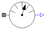
This is the base class of a 1D rotational component with one flange and one output signal in order to measure an absolute kinematic quantity in the flange and to provide the measured signal as output signal for further processing with the blocks of package Modelica.Blocks.
Release Notes:
partial model AbsoluteSensor
  "Base class to measure a single absolute flange variable"

  extends Modelica.Icons.RotationalSensor;
  Flange_a flange_a
    "(left) flange to be measured (flange axis directed INTO cut plane)";
  Modelica.Blocks.Interfaces.OutPort outPort(final n=1);
end AbsoluteSensor;
Modelica.Mechanics.Rotational.Interfaces.RelativeSensor
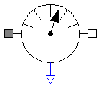
This is a base class for 1D rotational components with two rigidly connected flanges and one output signal in order to measure relative kinematic quantities between the two flanges or the cut-torque in the flange and to provide the measured signal as output signal for further processing with the blocks of package Modelica.Blocks.
Release Notes:
partial model RelativeSensor
  "Base class to measure a single relative variable between two flanges"


  extends Modelica.Icons.RotationalSensor;

  Flange_a flange_a
    "(left) driving flange (flange axis directed INTO cut plane)";
  Flange_b flange_b
    "(right) driven flange (flange axis directed OUT OF cut plane)";
  Modelica.Blocks.Interfaces.OutPort outPort(final n=1);
end RelativeSensor;