Test Scheduler
Test scheduler is a tool designed for handling test scheduling and test vector selection considering time constraints. As input, we assume a core-based architecture with n cores i where the following data is given as input:
- A benchmark consisting of information about the scanned elements (scan-chains, input cells, output cells and bidirectional cells).
- A data file consisting of information about pass probability ppi and fault coverage fci.
- Information whether hard cores or soft cores are used.
- An upper-bound time constraint Tmax.
- A maximal TAM bandwidth Wtam and the maximal number of TAMs k to use.
Test scheduler solves the problem of grouping the scanned elements into wrapper scan chains and creates a schedule for the cores. Test scheduler also returns a value of STQ to describe the test quality of the created schedule.
The functionality of Test scheduler is illustrated by Figure 1.
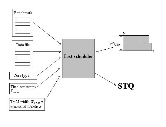
Figure 1 Test scheduling
To Use the Test Scheduler
The Test scheduler can be used either by using the GUI or by using a shell script. Before you can run the program, the input and the output need to be specified either by using the GUI or by running the program with the different options as arguments. Figure 2 shows a screenshot of the GUI.
If the GUI is used, the file where the output is stored can be selected from the File menu. The GUI consists of several panels grouped according to their purpose. Descriptions of the different panels can be seen below.
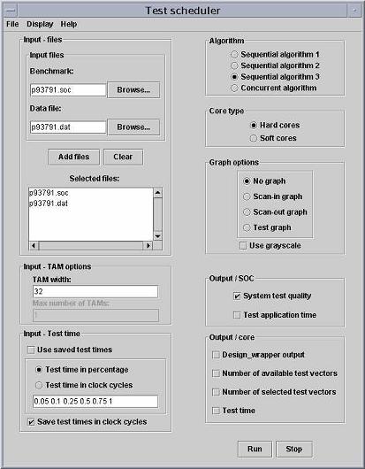
Figure 2 The GUI of Test scheduler
Files Panel
This panel allows you to specify which input files to use. In order to run the program, a benchmark need to be selected together with its corresponding data file. The files need to have identical names. For example if the benchmark d281.soc is used the data file is expected to be called d281.dat.
The files can be selected either by using the Browse bottoms to find the files and then click on the Add files bottom or to directly write the search path to the files in the Benchmark and the Data file text fields and then click the Add files bottom. It is possible to select several pairs of benchmarks and data files.
The TAM Options Panel
This panel allowes you to select the maximum TAM bandwidth and the maximum number of TAM's to use. The TAM width text field specifies the maximum TAM bandwidth, while the Max number of TAMs text field specifies the maximum number of TAMs (test buses) to use. In order to run the program for several bandwidths, separate the bandwidths with a space character.
The Test Time Panel
This panel allows you to specify the time constraint. The time constraint can be specified in three different ways:
Use an already saved test time by selecting the Use saved test times check box.
Select the Test time in percentage radio button and write a value between 0 and 1 in the text field. When this option is selected, the test time is given as a percentage of the time it would take to apply all test vectors assuming hard cores. 0 corresponds to 0% and 1 corresponds to 100%. In order to run the programs for several test times, separate the test times with a space character.
Select the Test time in clock cycles radio button and write the time constraint expressed in a number of clock cycles in the text field. Several test times can be selected in the same way as before.
One or several time constraints can be saved if the Save test times in clock cycles check box is selected. If test times given in percentage are saved, the test times are first transformed into clock cycles before they are saved.
The Algorithm Panel
This panel allows you to select the algorithm to use. It is possible to chose between four different algorithms:
If Sequential algorithm 1 is selected, defect probability and fault coverage are not considered during test ordering. Testing is terminated at tmax.
If Sequential algorithm 2 is selected, defect probability but not fault coverage are considered during test ordering. Testing is terminated at tmax.
If Sequential algorithm 3 is selected, defect probability and fault coverage are considered during test ordering. Testing is terminated at tmax.
If Concurrent algorithm is selected, test scheduling and test vector selection when considering defect probability and fault coverage are used. The number of TAMs to use is selected in...
The Core Type Panel
This panel allowes you to select the core type you want to use. It is possible to chose between:
Hard cores (fixed scan-chains as specified in the benchmark).
Soft cores (scanned flip-flops).
The Graph Options Panel
This panel allowes you to select the output to be displayed graphically. In this panel the following options can be selected:
When No graph option is selected, no graph is created.
Scan-in graph displays the scan-in lengths of the created scan chaines. A screen shot of a scen-in graph can be seen in Figure 3.
Scan-out graph displays the scan-out lengths of the created scan chaines. The look of the scan-out graph is similar to the look of the scan-in graph
Test graph displays the created schedule graphically. In this graph, the test time is always meassured in clockcycles. If the test time is given in percent, the test time is converted to clock cycles before it is displayed. An example of a test graph can be seen in figure 4.
Use grayscale checkbox can be selected if you want the graphs to be displayed in grayscale instead of in color.
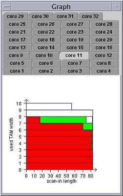
Figure 3 Graph displaying the grouping of scan chains, input cells and bidirectional I/O's
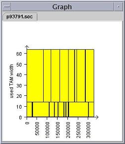
Figure 4 Graph desplaying the schedule
The Output/SOC Panel
This panel allowes you to select which output for the SOC that shall be printed out. The Options are:
System test quality shall be selected if you are interested in the STQ values for the SOC's.
Test application time shall be selected if you are interested in the test application times for the SOC's.
The Output/core Panel
This panel allowes you to select which output for the cores that shall be printed out. The Options are:
Design_wrapper output displays the output from the Design_wrapper algorithm such as scan-in length and scan-out length for the cores.
Number of available test vectors displays the number of available test vectors for each core.
Number of selected test vectors displays the number of selected test vectors for each core.
Test time displays the test application time in clock cycles for each core.
