 HyLibLight.Components.Basic.LamResNoStates
 HyLibLight.Components.Basic.LamResNoStates

LamResNoStates describes the laminar flow through a component.

q = G*dp

q   flow rate
G   conductance, m^3/(s * Pa)
dp  pressure drop across resistance

Equations to calculate the conductance G are given in the manual
for several components. A conductance of G = 4.167e-13 m^3/s/Pa
leads to a flow rate of 1 l/min at 4e7 Pa (=400 bar).

As the critical Reynolds number depends on the component there is
no check whether the flow is actually laminar or turbulent.

See also:

OrificeNoStates:	The model based on the loss coefficient K describes both flow regimes,
			laminar for very small Reynolds numbers, turbulent for higher
			Reynolds numbers (default model).
OriPolyNoStates:	The model describes both flow regimes, using a interpolation polynomial.
OriCavNoStates:		Orifice model checking for cavitation.
SimOriNoStates:		Texbook model, using a constant discharge coefficient
			(valid for turbulent flow only).
MeteringOriNoStates:	Metering Orifice, i. e. model OrificeNoStates with variable diameter.
TwoOrifices:		Two orifices in series, one with variable the other with
			fixed flow area.
OrificeN:		Same as OrificeNoStates, but equations rearranged to compute dp for
			given q.

Release Notes:
--------------

1999 - 10 - 24: tested
| Name | Default | Description |
|---|---|---|
| G | 4.2e-13 | conductance of laminar resistance [m3/(s*Pa)] |
model LamResNoStates "Resistance with laminar flow."
  extends HyLibLight.Interfaces.TwoPortComp;
  parameter HyLibLight.Interfaces.HyLibUnits.Conductance G=4.2e-13
    "conductance of laminar resistance";
equation
  q = G*dp;
end LamResNoStates;
Basic models of valves.


Flow and Pressure Control Valves
--------------------------------

These valves control the flow or pressure. They are modelled as
static systems. These models have no state variables.

CheckValveNoStates:	Ideal spring-loaded check valve with laminar/turbulent flow.
CheckValveTwoNoStates:	Ideal spring-loaded check valve with laminar/turbulent flow
			(different characteristics).
ShuttleValveNoStates:	Ideal shuttle valve with internal resistance (static model).
ReducingValveNoStates:	Ideal pressure reducing valve (static model).
SerFlowContNoStates:	Ideal series flow control valve (static model).


Spool Valves
------------

These valves control the flow according to the position of
the spool. The spool dynamics is modelled as a second order
system with limits for the spool velocity and position. There
are no lumped volumes connected at the ports.

ServoValveNoStates:	Valve with second order spool dynamics and nonlinearities. Flow area
			depends	linearly on spool position.
PropValveNoStates:	Valve with second order spool dynamics and nonlinearities. Flow area
			depends	not linearly on spool position, usually large overlap.
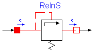
 HyLibLight.Components.Basic.ReliefValveNoStates

Ideal model of a relief valve

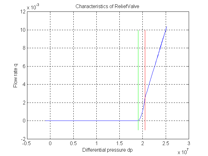
The resistance depends on the pressure differential dp = port_A.p - port_B.p

1) dp < pclosed => valve closed, only leakage
                   q = dp * GLeak

2) pclosed < dp < popen => working range,
                           i. e. valve partially opened

3) popen < dp => valve wide open
                 q = dp * GOpen

parameters for figure:	pclosed = 190e5 Pa
			popen   = 205e5 Pa
			GLeak   = 1.11e-12 m^3/(s*Pa)
			GOpen   = 1.666e-9 m^3/(s*Pa)

Release Notes:
--------------

1999 - 11 - 16: tested
| Name | Default | Description |
|---|---|---|
| pclosed | 190e5 | valve closed if dp smaller [Pa] |
| popen | 205e5 | valve wide open if dp higher [Pa] |
| GLeak | 1.111e-12 | conductance of closed valve, i. e. leakage [m3/(s*Pa)] |
| GOpen | 1.666e-9 | conductance of wide open valve [m3/(s*Pa)] |
model ReliefValveNoStates "Ideal model of a relief valve."
  extends HyLibLight.Interfaces.TwoPortComp;
  parameter Modelica.SIunits.Pressure pclosed(final min=0) = 190e5
    "valve closed if dp smaller";
  parameter Modelica.SIunits.Pressure popen=205e5
    "valve wide open if dp higher";
  parameter HyLibLight.Interfaces.HyLibUnits.Conductance GLeak=1.111e-12
    "conductance of closed valve, i. e. leakage";
  parameter HyLibLight.Interfaces.HyLibUnits.Conductance GOpen=1.666e-9
    "conductance of wide open valve";
  Boolean closed(start=false)
    "closed: .true. => valve closed, only leakage";
  Boolean open(start=false) "open : .true. => valve wide open";
equation
  closed = dp < pclosed;
  open = dp > popen;
  q = if closed then dp*GLeak else if open then (dp - pclosed)*GOpen + dp*
    GLeak else (dp - pclosed)^2*GOpen/(popen - pclosed) + dp*GLeak;

  assert(popen > pclosed,
    "Parameter popen MUST be greater than parameter pclosed.");

end ReliefValveNoStates;
 HyLibLight.Components.Basic.CheckValveNoStates

Spring-loaded check valve with laminar/turbulent flow

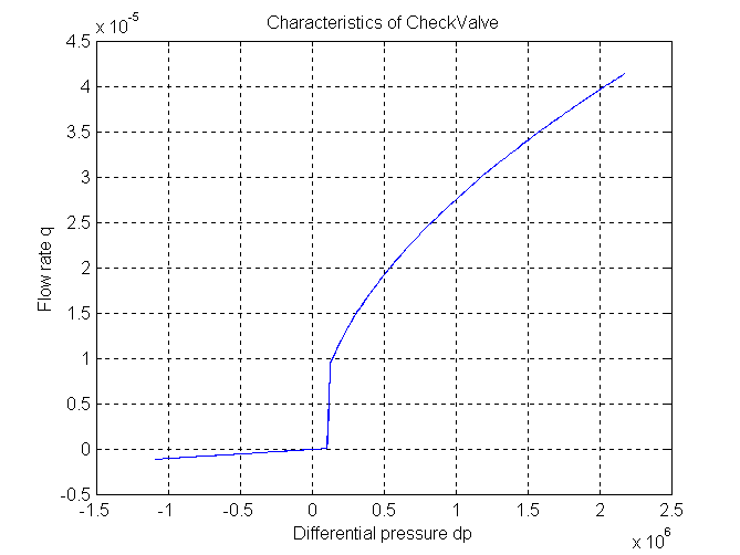
The resistance depends on the pressure differential

1) pressure differential dp < p_closed
   => q = dp * GLeak
      leakage from high pressure port to low pressure port only

2) p_closed < dp < p_open
   => valve is partially open

3) dp > p_open
   => valve is wide open,
      flow mode depends on Reynolds number
      resistance modelled as orifice parallel with laminar
      resistance (leakage)

The mass and flow forces are not included.

parameters for figure:	pclosed = 1e5 Pa
			popen = 1.25e5 Pa
			diameter = 1e-3
			GLeak=1.e-12 (very high value, for demonstration only)
			k1=10.
			k2=2.

Release Notes:
--------------

1999 - 11 - 16: tested
| Name | Default | Description |
|---|---|---|
| pclosed | 1e5 | pressure to start opening the valve [Pa] |
| popen | 1.25e5 | pressure to open valve completely [Pa] |
| diameter | 1.e-3 | diameter of equivalent orifice [m] |
| GLeak | 1.e-12 | conductance of leakage [m3/(s*Pa)] |
| k1 | 10. | laminar part [ ] |
| k2 | 2. | tubulent part, k2 = 1 / C_d^2 [ ] |
model CheckValveNoStates
  "Spring-loaded check valve with laminar/turbulent flow."
  extends HyLibLight.Components.Basic.CheckValvePartial;
  parameter Modelica.SIunits.Pressure pclosed(final min=0) = 1e5
    "pressure to start opening the valve";
  parameter Modelica.SIunits.Pressure popen(final min=0) = 1.25e5
    "pressure to open valve completely";
  parameter Modelica.SIunits.Diameter diameter=1.e-3
    "diameter of equivalent orifice";
  parameter HyLibLight.Interfaces.HyLibUnits.Conductance GLeak=1.e-12
    "conductance of leakage";
  parameter Real k1=10. "laminar part [ ]";
  parameter Real k2=2. "tubulent part, k2 = 1 / C_d^2 [ ]";
  Boolean closed(start=false) "valve closed, only leakage";
  Boolean open(start=false) "valve wide open";
  Real bopen;
  Modelica.SIunits.VolumeFlowRate qopen;
equation
  closed = dp < pclosed;
  open = dp > popen;
  qopen = (sqrt(k1^2*nu^2*rho^2 + 8*diameter^2*k2*noEvent(abs(popen))*rho) -
    k1*nu*rho)*diameter*Modelica.Constants.pi/(8*k2*rho);
  bopen = qopen/(popen - pclosed);
  port_A.q = if closed then dp*GLeak else if open then (sqrt(k1^2*nu^2*rho^2
     + 8*diameter^2*k2*noEvent(abs(dp))*rho) - k1*nu*rho)*diameter*Modelica.
    Constants.pi/(8*k2*rho) + dp*GLeak else (dp - pclosed)^2*bopen/(popen -
    pclosed) + dp*GLeak;

  assert(popen > pclosed,
    "Parameter popen MUST be greater than parameter pclosed.");
end CheckValveNoStates;
 HyLibLight.Components.Basic.VolumePartial

Partial model of a lumped volume, i. e. graphical information
model VolumePartial "Partial model of a lumped volume"
  extends HyLibLight.Interfaces.OnePortCompInput;
end VolumePartial;
 HyLibLight.Components.Basic.LineMiddle

     Class LineMiddle contains the equations for an element
     between the entrance and the exit element.
     The connectors are used to connect this element to another middle
     element of A to an entrance of B to an Exit element.
| Name | Default | Description |
|---|---|---|
| ElementLength | length of one element [m] | |
| diameter | line diameter [m] | |
| aSound | speed of sound in oil [m/s] |
model LineMiddle "Line element between entrance and exit."
  extends HyLibLight.Components.Basic.LineBase;
equation
  der(pk) = aSound/ElementLength*Zc*(qkminus - qkplus);
end LineMiddle;
 HyLibLight.Components.Basic.LineEntrance

     Class LineEntrance contains the equations for the entrance
     element, i. e. the beginning, of a long line.
     port_A is used to connect the long line to another
     hydraulic component.
| Name | Default | Description |
|---|---|---|
| ElementLength | length of one element [m] | |
| diameter | line diameter [m] | |
| aSound | speed of sound in oil [m/s] |
model LineEntrance "Entrance element of a long line."
  extends HyLibLight.Components.Basic.LineBase;
  Real ReynoldsNumber "Reynlods number";
equation
  ReynoldsNumber = qkminus*4/(diameter*Modelica.Constants.pi*nu);
  der(pk) = 2*aSound/ElementLength*Zc*(qkminus - qkplus);
end LineEntrance;
 HyLibLight.Components.Basic.LineExit

     Class LineExit contains the equations for the exit
     element, i. e. the end, of a long line.
     Connector port_B is used to connect the long line to another
     hydraulic component.
| Name | Default | Description |
|---|---|---|
| ElementLength | length of one element [m] | |
| diameter | line diameter [m] | |
| aSound | speed of sound in oil [m/s] |
model LineExit "Exit element of a long line."
  extends HyLibLight.Components.Basic.LineBase;
  Real ReynoldsNumber "Reynlods number";
equation
  der(pk) = 2*aSound/ElementLength*Zc*(qkminus - qkplus);
  ReynoldsNumber = qkminus*4/(diameter*Modelica.Constants.pi*nu);
end LineExit;
 HyLibLight.Components.Basic.CheckValvePartial

Partial model of a check valve, i. e. graphical information.
model CheckValvePartial
  "Partial model of a check valve, i. e. graphical information."
  extends HyLibLight.Interfaces.TwoPortComp;
  replaceable model Prop extends HyLibLight.Interfaces.FluidProp;  end Prop;
  extends Prop;
end CheckValvePartial;
 HyLibLight.Components.Basic.LineBase

     Class LineBase contains the equations and parameters
     that are needed for all long line classes.
| Name | Default | Description |
|---|---|---|
| ElementLength | length of one element [m] | |
| diameter | line diameter [m] | |
| aSound | speed of sound in oil [m/s] |
model LineBase "Base class for long line classes."

  replaceable model Prop extends HyLibLight.Interfaces.FluidProp;  end Prop;
  extends Prop;
  constant Real k1=0.1918;
  constant Real k2=0.0948;
  constant Real k3=0.0407;
  constant Real tau1=0.2496;
  constant Real tau2=0.0352;
  constant Real tau3=0.0024;
  Real alpha;
  Real Zc;
  Real wk1;
  Real wk2;
  Real wk3;
  parameter Modelica.SIunits.Length ElementLength
    "length of one element";
  parameter Modelica.SIunits.Diameter diameter "line diameter";
  parameter Modelica.SIunits.VelocityOfSound aSound
    "speed of sound in oil";
  Modelica.SIunits.Pressure pk;
  Modelica.SIunits.Pressure pkplus;
  Modelica.SIunits.VolumeFlowRate qkminus;
  Modelica.SIunits.VolumeFlowRate qkplus;
  HyLibLight.Interfaces.Port_A port_A
    "Port A, were oil flows into the component (positive q, port_A.p > port_B.p means positive dp)"
    ;
  HyLibLight.Interfaces.Port_B port_B
    "Port A, were oil leaves the component (negative q, port_A.p > port_B.p means positive dp)"
    ;
equation

  pk = port_A.p;
  pkplus = port_B.p;
  qkminus = port_A.q;
  qkplus = -port_B.q;
  alpha = 32*nu/diameter^2;
  Zc = aSound*rho/(diameter^2*Modelica.Constants.pi/4);
  der(wk1) = alpha*k1/tau1^2*Zc*qkplus - alpha/tau1*wk1;
  der(wk2) = alpha*k2/tau2^2*Zc*qkplus - alpha/tau2*wk2;
  der(wk3) = alpha*k3/tau3^2*Zc*qkplus - alpha/tau3*wk3;
  der(qkplus) = 1/Zc*(aSound/ElementLength*(pk - pkplus) - alpha*(1 + k1/tau1
     + k2/tau2 + k3/tau3)*Zc*qkplus + alpha*(wk1 + wk2 + wk3));
end LineBase;
 HyLibLight.Components.Basic.AccumulatorPartial

Partial model of an accumulator, i. e. graphical information
model AccumulatorPartial "Partial model of an accumulator" end
  AccumulatorPartial;
 HyLibLight.Components.Basic.ValveLogic

Switching logic for valve
| Name | Default | Description |
|---|---|---|
| pprecharge | 50e5 |
model ValveLogic "Switching logic for valve"

  parameter Real pprecharge=50e5;

  Modelica.Blocks.Interfaces.InPort inPort1(final n=1)
    "Connector of input signal used as flow rate";
  Modelica.Blocks.Interfaces.InPort inPort2(final n=1)
    "Connector of input signal used as flow rate";
  Modelica.Blocks.Interfaces.OutPort outPort(final n=1);
equation

  outPort.signal[1] = if (inPort1.signal[1] > pprecharge or inPort2.signal[
    1] > pprecharge) then 1 else 0;
end ValveLogic;
 HyLibLight.Components.Basic.CheckValvePartial.Prop
replaceable model Prop extends HyLibLight.Interfaces.FluidProp;end Prop;
 HyLibLight.Components.Basic.LineBase.Prop
replaceable model Prop extends HyLibLight.Interfaces.FluidProp;end Prop;