


This package contains electrical components with idealized behaviour:
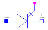
Modelica.Electrical.Analog.Ideal.IdealThyristor

Ideal thyristor ... < description will be added >
| Name | Default | Description |
|---|---|---|
| Roff | 1.E-5 | Closed thyristor resistance [Ohm] |
| Gon | 1.E-5 | Opened thyristor conductance [S] |
model IdealThyristor "Ideal thyristor"
  extends Interfaces.OnePort;
  parameter SI.Resistance Roff(final min=0) = 1.E-5 "Closed thyristor resistance";
  parameter SI.Conductance Gon(final min=0) = 1.E-5 "Opened thyristor conductance";
protected
  Real s "Auxiliary variable";
  Boolean off(start=true);
  Boolean fire(start=true);
public
  Modelica.Blocks.Interfaces.BooleanInPort firePort(final n=1);
equation
  fire = firePort.signal[1];
  off = s < 0 or pre(off) and not fire;
  v = s*(if off then 1 else Roff);
  i = s*(if off then Gon else 1);
end IdealThyristor;
Modelica.Electrical.Analog.Ideal.IdealGTOThyristor
Ideal GTO thyristor ...
| Name | Default | Description |
|---|---|---|
| Roff | 1.E-5 | Closed thyristor resistance [Ohm] |
| Gon | 1.E-5 | Opened thyristor conductance [S] |
model IdealGTOThyristor "Ideal GTO thyristor"
  extends Interfaces.OnePort;
  parameter SI.Resistance Roff(final min=0) = 1.E-5 "Closed thyristor resistance";
  parameter SI.Conductance Gon(final min=0) = 1.E-5 "Opened thyristor conductance";
protected
  Real s "Auxiliary variable";
  Boolean off(start=true) "Position of switch";
  Boolean fire;
public
  Modelica.Blocks.Interfaces.BooleanInPort firePort(final n=1);
equation
  fire = firePort.signal[1];
  off = s < 0 or not fire;
  v = s*(if off then 1 else Roff);
  i = s*(if off then Gon else 1);
end IdealGTOThyristor;
Modelica.Electrical.Analog.Ideal.IdealSwitch
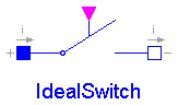
Ideal electrical switch. In order to prevent singularities during switching, the opened switch has a high resistance and the closed switch has a low resistance.
If the actual circuit has an appropriate structure, the limiting case is also allowed, i.e., the resistance of the closed switch could be exactly zero and the conductance of the open switch could be also exactly zero (i.e. the resistance is infinite). Note, there are circuits, where a description with zero/infinity resistances is not possible.
| Name | Default | Description |
|---|---|---|
| Roff | 1.E-5 | Closed switch resistance [Ohm] |
| Gon | 1.E-5 | Opened switch conductance [S] |
model IdealSwitch "Ideal electrical switch"
  extends Interfaces.OnePort;
  parameter SI.Resistance Roff(final min=0) = 1.E-5 "Closed switch resistance";
  parameter SI.Conductance Gon(final min=0) = 1.E-5 "Opened switch conductance";
protected
  Real s "Auxiliary variable";
  Boolean off;
public
  Modelica.Blocks.Interfaces.BooleanInPort control(final n=1, signal(start={
          false})) "true/false opened/closed switch";
equation
  off = control.signal[1];
  v = s*(if off then 1 else Roff);
  i = s*(if off then Gon else 1);
end IdealSwitch;
Modelica.Electrical.Analog.Ideal.IdealCommutingSwitch
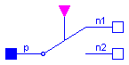
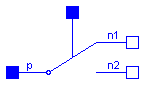
The commuting switch has a positive pin p and two negative pins n1 and n2. The switching behaviour is controlled by the control signal. If the control signal is true, the pin p is connected with the negative pin n2. Otherwise, the pin p is connected to the negative pin n1.
In order to prevent singularities during switching, the opened switch has a (very low) conductance Goff and the closed switch has a (very low) resistance Ron. The limiting case is also allowed, i.e., the resistance Ron of the closed switch could be exactly zero and the conductance Goff of the open switch could be also exactly zero. Note, there are circuits, where a description with zero Ron or zero Goff is not possible.
| Name | Default | Description |
|---|---|---|
| Ron | 1.E-5 | Closed switch resistance [Ohm] |
| Goff | 1.E-5 | Opened switch conductance [S] |
model IdealCommutingSwitch "Ideal commuting switch"
  parameter SI.Resistance Ron(final min=0) = 1.E-5 "Closed switch resistance";
  parameter SI.Conductance Goff(final min=0) = 1.E-5 "Opened switch conductance";
public
  Interfaces.PositivePin p;
  Interfaces.NegativePin n2;
  Interfaces.NegativePin n1;
  Modelica.Blocks.Interfaces.BooleanInPort control(final n=1)
    "true => p--n2 connected, false => p--n1 connected";
protected
  Real s1;
  Real s2 "Auxiliary variables";
  Boolean off;
equation
  off = control.signal[1];
  0 = p.i + n2.i + n1.i;

  p.v - n1.v = s1*(if (off) then 1 else Ron);
  n1.i = -s1*(if (off) then Goff else 1);
  p.v - n2.v = s2*(if (off) then Ron else 1);
  n2.i = -s2*(if (off) then 1 else Goff);
end IdealCommutingSwitch;
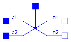
Modelica.Electrical.Analog.Ideal.IdealIntermediateSwitch
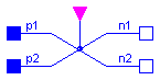
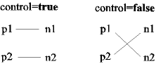
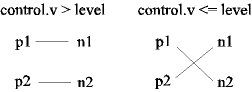
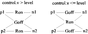
The intermediate switch has four switching contact pins p1, p2, n1, and n2. The switching behaviour is controlled by the control signal. If the control signal is true, the pin p1 is connected to pin n2, and the pin p2 is connected to the pin n2. Otherwise, the pin p1 is connected to n1, and p2 is connected to n2.
In order to prevent singularities during switching, the opened switch has a (very low) conductance Goff and the closed switch has a (very low) resistance Ron.
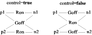
The limiting case is also allowed, i.e., the resistance Ron of the closed switch could be exactly zero and the conductance Goff of the open switch could be also exactly zero. Note, there are circuits, where a description with zero Ron or zero Goff is not possible.
| Name | Default | Description |
|---|---|---|
| Ron | 1.E-5 | Closed switch resistance [Ohm] |
| Goff | 1.E-5 | Opened switch conductance [S] |
model IdealIntermediateSwitch "Ideal intermediate switch"
  parameter SI.Resistance Ron(final min=0) = 1.E-5 "Closed switch resistance";
  parameter SI.Conductance Goff(final min=0) = 1.E-5 "Opened switch conductance";
public
  Interfaces.PositivePin p1;
  Interfaces.PositivePin p2;
  Interfaces.NegativePin n1;
  Interfaces.NegativePin n2;
  Modelica.Blocks.Interfaces.BooleanInPort control(final n=1) "true => p1--n2, p2--n1 connected,
         otherwise p1--n1, p2--n2  connected";
protected
  Real s1;
  Real s2;
  Real s3;
  Real s4 "Auxiliary variables";
  Boolean off;
equation
  off = control.signal[1];
  p1.v - n1.v = s1*(if (off) then 1 else Ron);
  p2.v - n2.v = s2*(if (off) then 1 else Ron);
  p1.v - n2.v = s3*(if (off) then Ron else 1);
  p2.v - n1.v = s4*(if (off) then Ron else 1);

  p1.i = if (off) then s1*Goff + s3 else s1 + s3*Goff;
  p2.i = if (off) then s2*Goff + s4 else s2 + s4*Goff;
  n1.i = if (off) then -s1*Goff - s4 else -s1 - s4*Goff;
  n2.i = if (off) then -s2*Goff - s3 else -s2 - s3*Goff;
end IdealIntermediateSwitch;
Modelica.Electrical.Analog.Ideal.ControlledIdealSwitch
The ideal switch is a three-pole. If the third pin voltage exceeds the given parameter Voltage, the pins p and n are open (no current flowing, any voltage possible). Otherwise, p and n are short cut.
| Name | Default | Description |
|---|---|---|
| level | 0.5 | Switch level [V] |
| Roff | 1.E-5 | Closed switch resistance [Ohm] |
| Gon | 1.E-5 | Opened switch conductance [S] |
model ControlledIdealSwitch "Controlled ideal switch"
  parameter SI.Voltage level=0.5 "Switch level";
  parameter SI.Resistance Roff(final min=0) = 1.E-5 "Closed switch resistance";
  parameter SI.Conductance Gon(final min=0) = 1.E-5 "Opened switch conductance";
protected
  Real s "Auxiliary variable";
public
  Interfaces.Pin p "Positive pin";
  Interfaces.Pin n "Negative pin";
  Interfaces.Pin control
    "Control pin: control.v > level open, otherwise closed";
equation
  control.i = 0;
  0 = p.i + n.i;
  p.v - n.v = s*(if (control.v < level) then Roff else 1);
  n.i = s*(if (control.v < level) then 1 else Gon);
end ControlledIdealSwitch;
Modelica.Electrical.Analog.Ideal.ControlledIdealCommutingSwitch
The commuting switch has a positive pin p and two negative pins n1 and n2. The switching behaviour is controlled by the control pin. If its voltage exceeds the value of the parameter level, the pin p is connected with the negative pin n2. Otherwise, the pin p is connected the negative pin n1.
In order to prevent singularities during switching, the opened switch has a (very low) conductance Goff and the closed switch has a (very low) resistance Ron. The limiting case is also allowed, i.e., the resistance Ron of the closed switch could be exactly zero and the conductance Goff of the open switch could be also exactly zero. Note, there are circuits, where a description with zero Ron or zero Goff is not possible.
| Name | Default | Description |
|---|---|---|
| level | 0.5 | Switch level [V] |
| Ron | 1.E-5 | Closed switch resistance [Ohm] |
| Goff | 1.E-5 | Opened switch conductance [S] |
model ControlledIdealCommutingSwitch
  "Controlled ideal commuting switch"
  parameter SI.Voltage level=0.5 "Switch level";
  parameter SI.Resistance Ron(final min=0) = 1.E-5 "Closed switch resistance";
  parameter SI.Conductance Goff(final min=0) = 1.E-5 "Opened switch conductance";
public
  Interfaces.PositivePin p;
  Interfaces.NegativePin n2;
  Interfaces.NegativePin n1;
  Interfaces.Pin control
    "Control pin: if control.v > level p--n2 connected, otherwise p--n1 connected"
    ;
protected
  Real s1;
  Real s2 "Auxiliary variables";
equation
  control.i = 0;
  0 = p.i + n2.i + n1.i;

  p.v - n1.v = s1*(if (control.v > level) then 1 else Ron);
  n1.i = -s1*(if (control.v > level) then Goff else 1);
  p.v - n2.v = s2*(if (control.v > level) then Ron else 1);
  n2.i = -s2*(if (control.v > level) then 1 else Goff);
end ControlledIdealCommutingSwitch;
Modelica.Electrical.Analog.Ideal.ControlledIdealIntermediateSwitch
The intermediate switch has four switching contact pins p1, p2, n1, and n2. The switching behaviour is controlled by the control pin. If its voltage exceeds the value of the parameter level, the pin p1 is connected to pin n2, and the pin p2 is connected to the pin n2. Otherwise, the pin p1 is connected to n1, and p2 is connected to n2.
In order to prevent singularities during switching, the opened switch has a (very low) conductance Goff and the closed switch has a (very low) resistance Ron.
The limiting case is also allowed, i.e., the resistance Ron of the closed switch could be exactly zero and the conductance Goff of the open switch could be also exactly zero. Note, there are circuits, where a description with zero Ron or zero Goff is not possible.
| Name | Default | Description |
|---|---|---|
| level | 0.5 | Switch level [V] |
| Ron | 1.E-5 | Closed switch resistance [Ohm] |
| Goff | 1.E-5 | Opened switch conductance [S] |
model ControlledIdealIntermediateSwitch
  "Controlled ideal intermediate switch"
  parameter SI.Voltage level=0.5 "Switch level";
  parameter SI.Resistance Ron(final min=0) = 1.E-5 "Closed switch resistance";
  parameter SI.Conductance Goff(final min=0) = 1.E-5 "Opened switch conductance";

public
  Interfaces.PositivePin p1;
  Interfaces.PositivePin p2;
  Interfaces.NegativePin n1;
  Interfaces.NegativePin n2;
  Interfaces.Pin control "Control pin: if control.v > level p1--n2, p2--n1 connected,
         otherwise p1--n1, p2--n2  connected";
protected
  Real s1;
  Real s2;
  Real s3;
  Real s4 "Auxiliary variables";
equation
  control.i = 0;

  p1.v - n1.v = s1*(if (control.v > level) then 1 else Ron);
  p2.v - n2.v = s2*(if (control.v > level) then 1 else Ron);
  p1.v - n2.v = s3*(if (control.v > level) then Ron else 1);
  p2.v - n1.v = s4*(if (control.v > level) then Ron else 1);

  p1.i = if (control.v > level) then s1*Goff + s3 else s1 + s3*Goff;
  p2.i = if (control.v > level) then s2*Goff + s4 else s2 + s4*Goff;
  n1.i = if (control.v > level) then -s1*Goff - s4 else -s1 - s4*Goff;
  n2.i = if (control.v > level) then -s2*Goff - s3 else -s2 - s3*Goff;
end ControlledIdealIntermediateSwitch;
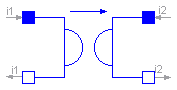
Modelica.Electrical.Analog.Ideal.IdealOpAmp
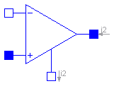
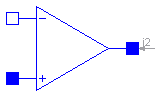
The ideal OpAmp is a two-port. The left port is fixed to v1=0 and i1=0 (nullator). At the right port both any voltage v2 and any current i2 are possible (norator).
model IdealOpAmp
  "Ideal operational amplifier (norator-nullator pair)"
  SI.Voltage v1 "Voltage drop over the left port";
  SI.Voltage v2 "Voltage drop over the right port";
  SI.Current i1 "Current flowing from pos. to neg. pin of the left port";
  SI.Current i2 "Current flowing from pos. to neg. pin of the right port";
  Interfaces.PositivePin p1 "Positive pin of the left port";
  Interfaces.NegativePin n1 "Negative pin of the left port";
  Interfaces.PositivePin p2 "Positive pin of the right port";
  Interfaces.NegativePin n2 "Negative pin of the right port";
equation
  v1 = p1.v - n1.v;
  v2 = p2.v - n2.v;
  0 = p1.i + n1.i;
  0 = p2.i + n2.i;
  i1 = p1.i;
  i2 = p2.i;
  v1 = 0;
  i1 = 0;
end IdealOpAmp;
Modelica.Electrical.Analog.Ideal.IdealOpAmp3Pin
The ideal OpAmp with three pins is of exactly the same behaviour as the ideal OpAmp with four pins. Only the negative output pin is left out. Both the input voltage and current are fixed to zero (nullator). At the output pin both any voltage v2 and any current i2 are possible.
model IdealOpAmp3Pin
  "Ideal operational amplifier (norator-nullator pair), but 3 pins"
  Interfaces.PositivePin in_p "Positive pin of the input port";
  Interfaces.NegativePin in_n "Negative pin of the input port";
  Interfaces.PositivePin out "Output pin";
equation
  in_p.v = in_n.v;
  in_p.i = 0;
  in_n.i = 0;
end IdealOpAmp3Pin;
Modelica.Electrical.Analog.Ideal.IdealOpAmpLimited
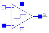
The ideal OpAmp with limitation behaves like an ideal OpAmp without limitation, if the output voltage is within the limits (VMin < out.v < VMax). In this case the input voltage vin=in_p.v - in_n.v is zero. If the input voltage is vin < 0, the output voltage is out.v = VMin. If the input voltage is vin > 0, the output voltage is out.v = VMax.
model IdealOpAmpLimited "Ideal operational amplifier with limitation"

  Interfaces.PositivePin in_p "Positive pin of the input port";
  Interfaces.NegativePin in_n "Negative pin of the input port";
  Interfaces.PositivePin out "Output pin";
  Interfaces.PositivePin VMax "Positive output voltage limitation";
  Interfaces.NegativePin VMin "Negative output voltage limitation";
  SI.Voltage vin "input voltage";
protected
  Real s "Auxiliary variable";
equation
  in_p.i = 0;
  in_n.i = 0;
  VMax.i = 0;
  VMin.i = 0;
  vin = in_p.v - in_n.v;
  in_p.v - in_n.v = if (s < -1) then s + 1 else if (s > 1) then s - 1 else 0;
  out.v = if (s < -1) then VMin.v else if (s > 1) then VMax.v else (VMax.v -
    VMin.v)*s/2 + (VMax.v + VMin.v)/2;
end IdealOpAmpLimited;
Modelica.Electrical.Analog.Ideal.IdealDiode
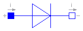
Ideal electrical diode. This is an ideal switch which is open, when it is reversed biased (voltage drop < 0) and which is closed, when it is conducting (current > 0). In order to prevent singularities during switching, the opened diode has a high resistance and the closed diode has a low resistance.
If the actual circuit has an appropriate structure, the limiting case is also allowed, i.e., the resistance of the closed diode could be exactly zero and the conductance of the open diode could be also exactly zero (i.e. the resistance is infinity). Note, there are circuits, where a description with zero/infinity resistances is not possible.
| Name | Default | Description |
|---|---|---|
| Roff | 1.E-5 | Closed diode resistance [Ohm] |
| Gon | 1.E-5 | Opened diode conductance [S] |
model IdealDiode "Ideal electrical diode"
  extends Interfaces.OnePort;
  parameter SI.Resistance Roff(final min=0) = 1.E-5 "Closed diode resistance";
  parameter SI.Conductance Gon(final min=0) = 1.E-5 "Opened diode conductance";
  Boolean off(start=true) "Switching state of diode";
protected
  Real s "Auxiliary variable";
equation
  off = s < 0;
  v = s*(if off then 1 else Roff);
  i = s*(if off then Gon else 1);
end IdealDiode;
Modelica.Electrical.Analog.Ideal.IdealTransformer
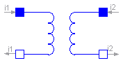
The ideal transformer is an ideal two-port resistive circuit element which is characterized by the following two equations:
    v1 =  n * v2
    i2 = -n * i1
where n is a real number called the turns ratio.
| Name | Default | Description |
|---|---|---|
| n | 1 | Turns ratio |
model IdealTransformer "Ideal electrical transformer"
  extends Interfaces.TwoPort;
  parameter Real n=1 "Turns ratio";
equation
  v1 = n*v2;
  i2 = -n*i1;
end IdealTransformer;
Modelica.Electrical.Analog.Ideal.IdealGyrator
A gyrator is an ideal two-port element defined by the following equations:
    i1 =  G * v2
    i2 = -G * v1
where the constant G is called the gyration conductance.
| Name | Default | Description |
|---|---|---|
| G | 1 | Gyration conductance [S] |
model IdealGyrator "Ideal gyrator"
  extends Interfaces.TwoPort;
  parameter SI.Conductance G=1 "Gyration conductance";
equation
  i1 = G*v2;
  i2 = -G*v1;
end IdealGyrator;
Modelica.Electrical.Analog.Ideal.Idle
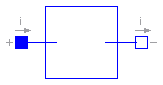
The model Idle is a simple idle running branch.
model Idle "Idle branch"
  extends Interfaces.OnePort;
equation

  i = 0;

end Idle;
Modelica.Electrical.Analog.Ideal.Short
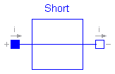
The model Short is a simple short cut branch.
model Short "Short cut branch"
  extends Interfaces.OnePort;
equation
  v = 0;
end Short;
Modelica.Electrical.Analog.Ideal.IdealOpener
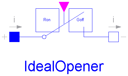
The ideal opener has a positive pin p and a negative pin n. The switching behaviour is controlled by the control signal. If the control signal is true, pin p is not connected with negative pin n. Otherwise, pin p is connected with negative pin n.
In order to prevent singularities during switching, the opened switch has a (very low) conductance Goff and the closed switch has a (very low) resistance Ron. The limiting case is also allowed, i.e., the resistance Ron of the closed switch could be exactly zero and the conductance Goff of the open switch could be also exactly zero. Note, there are circuits, where a description with zero Ron or zero Goff is not possible.
| Name | Default | Description |
|---|---|---|
| Ron | 1.E-5 | Closed switch resistance [Ohm] |
| Goff | 1.E-5 | Opened switch conductance [S] |
model IdealOpener "Ideal electrical opener"
  extends Interfaces.OnePort;
  parameter SI.Resistance Ron(final min=0) = 1.E-5 "Closed switch resistance";
  parameter SI.Conductance Goff(final min=0) = 1.E-5 "Opened switch conductance";
  Modelica.Blocks.Interfaces.BooleanInPort control(final n=1)
    "true => switch open, false => p--n connected";
protected
  Real s "Auxiliary variable";
  Boolean off;

equation
  off = control.signal[1];
  v = s*(if off then 1 else Ron);
  i = s*(if off then Goff else 1);
end IdealOpener;
Modelica.Electrical.Analog.Ideal.IdealCloser
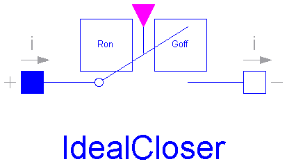
The ideal opener has a positive pin p and a negative pin n. The switching behaviour is controlled by the control signal. If the control signal is true, pin p is not connected with negative pin n. Otherwise, pin p is connected with negative pin n.
In order to prevent singularities during switching, the opened switch has a (very low) conductance Goff and the closed switch has a (very low) resistance Ron. The limiting case is also allowed, i.e., the resistance Ron of the closed switch could be exactly zero and the conductance Goff of the open switch could be also exactly zero. Note, there are circuits, where a description with zero Ron or zero Goff is not possible.
| Name | Default | Description |
|---|---|---|
| Ron | 1.E-5 | Closed switch resistance [Ohm] |
| Goff | 1.E-5 | Opened switch conductance [S] |
model IdealCloser "Ideal electrical closer"
  extends Interfaces.OnePort;
  parameter SI.Resistance Ron(final min=0) = 1.E-5 "Closed switch resistance";
  parameter SI.Conductance Goff(final min=0) = 1.E-5 "Opened switch conductance";
  Modelica.Blocks.Interfaces.BooleanInPort control(final n=1)
    "true => switch open, false => p--n connected";
protected
  Real s "Auxiliary variable";
  Boolean on;

equation
  on = control.signal[1];
  v = s*(if not on then 1 else Ron);
  i = s*(if not on then Goff else 1);
end IdealCloser;
Modelica.Electrical.Analog.Ideal.ControlledIdealOpener
The ideal switch has a positive pin p and a negative pin n. The switching behaviour is controlled by the control pin. If its voltage exceeds the voltage of the parameter level, pin p is not connected with negative pin n. Otherwise, pin p is connected with negative pin n.
In order to prevent singularities during switching, the opened switch has a (very low) conductance Goff and the closed switch has a (very low) resistance Ron. The limiting case is also allowed, i.e., the resistance Ron of the closed switch could be exactly zero and the conductance Goff of the open switch could be also exactly zero. Note, there are circuits, where a description with zero Ron or zero Goff is not possible.
| Name | Default | Description |
|---|---|---|
| level | 0.5 | Switch level [V] |
| Ron | 1.E-5 | Closed switch resistance [Ohm] |
| Goff | 1.E-5 | Opened switch conductance [S] |
model ControlledIdealOpener "Controlled ideal electrical opener"
  parameter SI.Voltage level=0.5 "Switch level";
  parameter SI.Resistance Ron(final min=0) = 1.E-5 "Closed switch resistance";
  parameter SI.Conductance Goff(final min=0) = 1.E-5 "Opened switch conductance";
protected
  Real s "Auxiliary variable";
public
  Interfaces.PositivePin p;
  Interfaces.NegativePin n;
  Interfaces.Pin control
    "Control pin: control.v > level switch open, otherwise p--n connected";
equation
  control.i = 0;
  0 = p.i + n.i;
  p.v - n.v = s*(if (control.v > level) then 1 else Ron);
  p.i = s*(if (control.v > level) then Goff else 1);
end ControlledIdealOpener;
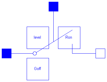
Modelica.Electrical.Analog.Ideal.ControlledIdealCloser

The ideal switch has a positive pin p and a negative pin n. The switching behaviour is controlled by the control pin. If its voltage exceeds the voltage of the parameter level, pin p is not connected with negative pin n. Otherwise, pin p is connected with negative pin n.
In order to prevent singularities during switching, the opened switch has a (very low) conductance Goff and the closed switch has a (very low) resistance Ron. The limiting case is also allowed, i.e., the resistance Ron of the closed switch could be exactly zero and the conductance Goff of the open switch could be also exactly zero. Note, there are circuits, where a description with zero Ron or zero Goff is not possible.
| Name | Default | Description |
|---|---|---|
| level | 0.5 | Switch level [V] |
| Ron | 1.E-5 | Closed switch resistance [Ohm] |
| Goff | 1.E-5 | Opened switch conductance [S] |
model ControlledIdealCloser "Controlled ideal electrical closer"
  parameter SI.Voltage level=0.5 "Switch level";
  parameter SI.Resistance Ron(final min=0) = 1.E-5 "Closed switch resistance";
  parameter SI.Conductance Goff(final min=0) = 1.E-5 "Opened switch conductance";
protected
  Real s "Auxiliary variable";
public
  Interfaces.PositivePin p;
  Interfaces.NegativePin n;
  Interfaces.Pin control
    "Control pin: control.v > level switch open, otherwise p--n connected";
equation
  control.i = 0;
  0 = p.i + n.i;
  p.v - n.v = s*(if (control.v > level) then Ron else 1);
  p.i = s*(if (control.v > level) then 1 else Goff);
end ControlledIdealCloser;