


Basic models of pumps and motors.

TankNoRes		Tank, i. e. constant pressure outlet, but no resistance
IdFlowSource 		ideal flow source
IdFlowSourceExtCommand 	ideal flow source with externally commanded flow rate
IdConPump		ideal pump with constant displacement
IdVarPump		ideal pump with variable displacement
IdConMot		ideal motor with constant displacement
IdVarMot		ideal motor with variable displacement

DieselNoStates		Diesel motor with speed controller but no inertia
AsynchronNoStates	electrical asynchron motor without inertia


Release Notes:
--------------

1999 - 10 - 13: coded
 HyLibLight.Pumps.Basic.DieselNoStates
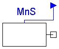
Diesel engine with speed controller but no inertia

The model uses a static characteristic curve of maximum torque as a
function of speed. This relation is given by a polynomial.

There is a simple speed controller implemented. The reference signal
for this controller is given by

          inPort.signal = 0 => w_min
          inPort.signal = 1 => w_max

This simple model doesn't describe the startup of a Diesel engine.
(Set initial conditions for coupled inertia between w_min and w_max.)


Release Notes:
--------------

2000 - 1 - 28: tested
| Name | Default | Description |
|---|---|---|
| wmin | 75 | minimum angular velocity [rad/s] |
| wmax | 240 | maximum angular velocity [rad/s] |
| diesel3 | 9.0212e-6 | |
| diesel2 | -7.5153e-3 | |
| diesel1 | 1.5939 | |
| diesel0 | 7.5022e+1 | |
| kdiesel | 10 | gain of speed controller, Nm / (rad/sec) |
model DieselNoStates "Diesel engine with speed controller"
  parameter Modelica.SIunits.AngularVelocity wmin=75
    "minimum angular velocity";
  parameter Modelica.SIunits.AngularVelocity wmax=240
    "maximum angular velocity";
  parameter Real diesel3=9.0212e-6;
  parameter Real diesel2=-7.5153e-3;
  parameter Real diesel1=1.5939;
  parameter Real diesel0=7.5022e+1;
  parameter Real kdiesel=10
    "gain of speed controller, Nm / (rad/sec)";

  Modelica.SIunits.AngularVelocity wRefu;
  Modelica.SIunits.AngularVelocity wRef;
  Modelica.SIunits.AngularVelocity w
    "absolute angular velocity of component";
  Modelica.SIunits.Torque taumax;
  Modelica.SIunits.Torque tauref;

  Modelica.Mechanics.Rotational.Interfaces.Flange_b flange_b
    "(right) driven flange (flange axis directed OUT OF cut plane)";
  Modelica.Blocks.Interfaces.InPort inPort(final n=1)
    "Connector of input signal used as commanded speed";
equation
  w = der(flange_b.phi);

  wRefu = wmin + (wmax - wmin)*inPort.signal[1];
  /*unlimited command signal*/

  wRef = if (wRefu < wmin) then wmin else if (wRefu > wmax) then wmax
     else wRefu;
  /*limited command signal*/

  tauref = (wRef - w)*kdiesel;
  taumax = diesel0 + diesel1*w + diesel2*w*w + diesel3*w*w*w;

  -flange_b.tau = if (w < 0.5*wmin) then -5*w else if (tauref > taumax)
     then taumax else if (tauref < -0.3*taumax) then -0.3*taumax else tauref
    ;

end DieselNoStates;
 HyLibLight.Pumps.Basic.IdVarPump
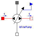
Ideal pump with variable displacement

Flow of an ideal pump with variable displacement

The flow rate is given by:

q = Dpump * w * inPort.signal[1] / (2 * pi)

if the inlet pressure is higher than the atmospheric pressure,
otherwise the delivered flow becomes smaller.

q:       		delivered flow rate in m^3/s
Dpump:   		displacement per revolution in m^3
w:      		angular velocity in rad/s
inPort.signal[1]:  	command signal for relative displacement:
         		+1 => max. flow from A -> B (for w > 0)
          	  	 0 => q = 0
         		-1 => max. flow from B -> A (for w > 0)


Release Notes:
--------------

2000 - 2 - 1: tested
| Name | Default | Description |
|---|---|---|
| Dpump | 0.1e-3 | displacement per revolution [m3] |
model IdVarPump "Ideal pump with variable displacement."
  extends HyLibLight.Interfaces.RotComp;
  parameter Modelica.SIunits.Volume Dpump=0.1e-3
    "displacement per revolution";
  Real sig;
  Real factor;
  Modelica.Blocks.Interfaces.InPort inPort(final n=1)
    "Connector of input signal used as relative displacement volume";
equation
  sig = if inPort.signal[1] < -1 then -1 else if inPort.signal[1] > 1
     then 1 else inPort.signal[1];
  factor = if (sig*w > 0 and port_A.p < pvapour) then 0 else if (sig*w
     > 0 and port_A.p < 0) then (1 - (1 + (port_A.p - pvapour)/pvapour)^2
    ) else if (sig*w < 0 and port_B.p < pvapour) then 0 else if (sig*w
     < 0 and port_B.p < 0) then (1 - (1 + (port_B.p - pvapour)/pvapour)^2
    ) else 1;
  q = Dpump*w*sig/(2*Modelica.Constants.pi)*factor;
  -Dpump*sig*dp*factor/(2*Modelica.Constants.pi) = flange_a.tau + flange_b.tau
    ;
end IdVarPump;
 HyLibLight.Pumps.Basic.IdConPump
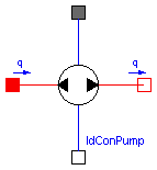
Ideal pump with constant displacement

The flow rate is given by:

q = Dpump * w / (2 * pi)

if the inlet pressure is higher than the atmospheric pressure,
otherwise the delivered flow becomes smaller.

q:       delivered flow rate in m^3/s
Dpump:   displacement per revolution in m^3
w:       angular velocity in rad/s


Release Notes:
--------------

1999 - 10 - 26: tested
| Name | Default | Description |
|---|---|---|
| Dpump | 0.1e-3 | displacement per revolution [m3] |
model IdConPump "Ideal pump with constant displacement."
  extends HyLibLight.Interfaces.RotComp;
  parameter Modelica.SIunits.Volume Dpump=0.1e-3
    "displacement per revolution";
  Real factor;
equation
  factor = if (w > 0 and port_A.p < pvapour) then 0 else if (w > 0
     and port_A.p < 0) then (1 - (1 + (port_A.p - pvapour)/pvapour)^2) else
    if (w < 0 and port_B.p < pvapour) then 0 else if (w < 0 and port_B
    .p < 0) then (1 - (1 + (port_B.p - pvapour)/pvapour)^2) else 1;
  q = Dpump*w/(2*Modelica.Constants.pi)*factor;
  -Dpump*dp*factor/(2*Modelica.Constants.pi) = flange_a.tau + flange_b.tau;
end IdConPump;
 HyLibLight.Pumps.Basic.TankNoRes
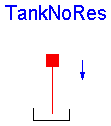
Tank with a preload pressure against atmosphere.

A preload pressure of 0 Pa means that the tank
has atmospheric pressure.
A preload pressure of 1 MPa means that the tank
has an absolute pressure of 1,1 Mpa.

See also:

Tank	Tank with preload and a laminar resistance (line)


Release Notes:
--------------

1999 - 10 - 18: tested
| Name | Default | Description |
|---|---|---|
| ppreload | 0.0e5 | preload pressure [Pa] |
model TankNoRes "Tank with preload."
  extends HyLibLight.Interfaces.OnePortCompInput90;

  parameter Modelica.SIunits.Pressure ppreload=0.0e5
    "preload pressure";
equation
  port_A.p = ppreload;

end TankNoRes;
 HyLibLight.Pumps.Basic.IdConMot
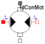
Ideal motor with constant displacement

The flow rate q is given by

q = Dmotor * w / (2 * pi)

if the pressure at the inlet port is higher than the atmoshperic
pressure, otherwise there is a flow reduction.

q:       flow rate in m^3/s
Dmotor:  displacement in m^3 / revolution
w:       angular velocity in rad/s

The torque tau is given by:

tau = Dmotor * (pA - pB)/(2*pi)


Release Notes:
--------------

1999 - 10 - 26: tested
| Name | Default | Description |
|---|---|---|
| Dmotor | 0.1e-3 | displacement per revolution [m3] |
model IdConMot "Ideal constant displacement motor."
  extends HyLibLight.Interfaces.RotComp;

  parameter Modelica.SIunits.Volume Dmotor=0.1e-3
    "displacement per revolution";
  Real factor;

equation
  factor = if (w > 0 and port_A.p < pvapour) then 0 else if (w > 0
     and port_A.p < 0) then (1 - (1 + (port_A.p - pvapour)/pvapour)^2) else
    if (w < 0 and port_B.p < pvapour) then 0 else if (w < 0 and port_B
    .p < 0) then (1 - (1 + (port_B.p - pvapour)/pvapour)^2) else 1;
  q = Dmotor*w*factor/(2*Modelica.Constants.pi);
  -dp*Dmotor*factor/(2*Modelica.Constants.pi) = flange_a.tau + flange_b.tau;
end IdConMot;
 HyLibLight.Pumps.Basic.IdFlowSource
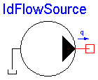
Flow of an ideal flow source

The flow rate is given by:

q = qbias + qamp * sin(qfreq * 2 * pi * time + qphase)

The flow can become negative.

The pressure is a result of the flow and the following resistances.


Release Notes:
--------------

1999 - 10 - 18: tested
| Name | Default | Description |
|---|---|---|
| qbias | 1e-3 | bias of flow [m3/s] |
| qamp | 0 | amplitude of sinusoidal flow [m3/s] |
| qfreq | 0 | frequency of sinusoidal flow [Hz] |
| qphase | 0 | rad; phase shift |
model IdFlowSource "Ideal flow source."
  extends HyLibLight.Interfaces.OnePortCompOutput;

  parameter Modelica.SIunits.VolumeFlowRate qbias=1e-3
    "bias of flow";
  parameter Modelica.SIunits.VolumeFlowRate qamp=0
    "amplitude of sinusoidal flow";
  parameter Modelica.SIunits.Frequency qfreq=0
    "frequency of sinusoidal flow";
  parameter Real qphase=0 "rad; phase shift";
equation
  -port_B.q = qbias + qamp*Modelica.Math.sin(qfreq*6.28319*time + qphase);
end IdFlowSource;
 HyLibLight.Pumps.Basic.IdFlowSourceExtCommand
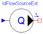
Ideal flow source with externally commanded flow rate.

The flow rate is given by inPort.signal in m^3/s.The flow rate
can become negative. The pressure is a result of the flow rate
and the following resistances.


Release Notes:
--------------

2000 - 1 - 24: tested
model IdFlowSourceExtCommand
  "Ideal flow source with externally commanded flow rate."
  extends HyLibLight.Interfaces.OnePortCompOutput;
  Modelica.Blocks.Interfaces.InPort inPort(final n=1)
    "Connector of input signal used as flow rate";
equation
  -port_B.q = inPort.signal[1];
end IdFlowSourceExtCommand;
 HyLibLight.Pumps.Basic.IdVarMot
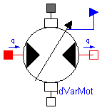
Ideal motor with variable displacement.

The flow rate q is given by:

q = Dmotor * inPort.signal[1] * w / (2 * pi)

if the pressure at the inlet port is higher than the atmoshperic
pressure, otherwise there is a flow reduction.

q:       		flow rate in m^3/s
Dmotor:  		displacement in m^3 / revolution
w:       		angular velocity in rad/s
inPort.signal[1]:	command signal for relative displacement

The torque tau is given by:

tau = Dmotor * inPort.signal[1] * (pA - pB)/(2*pi)


inPort.signal[1]:  	command signal for relative displacement:
           		+1 => max. flow from A -> B (for omega > 0)
            		 0 => q = 0
           		-1 => max. flow from B -> A (for omega > 0)

Release Notes:
--------------

2000 - 1 - 27: tested
| Name | Default | Description |
|---|---|---|
| Dmotor | 0.1e-3 | max. displacement per revolution [m3] |
model IdVarMot "Ideal variable displacement motor."
  extends HyLibLight.Interfaces.RotComp;
  parameter Modelica.SIunits.Volume Dmotor=0.1e-3
    "max. displacement per revolution";
  Real factor;
  Real sig;

  Modelica.Blocks.Interfaces.InPort inPort(final n=1)
    "Connector of input signal used as relative displacement volume";
equation

  sig = if inPort.signal[1] < -1 then -1 else if inPort.signal[1] > 1
     then 1 else inPort.signal[1];
  factor = if (sig*w > 0 and port_A.p < pvapour) then 0 else if (sig*w
     > 0 and port_A.p < 0) then (1 - (1 + (port_A.p - pvapour)/pvapour)^2
    ) else if (sig*w < 0 and port_B.p < pvapour) then 0 else if (sig*w
     < 0 and port_B.p < 0) then (1 - (1 + (port_B.p - pvapour)/pvapour)^2
    ) else 1;
  q = Dmotor*w*sig/(2*Modelica.Constants.pi)*factor;
  -dp*Dmotor*factor*sig/(2*Modelica.Constants.pi) = flange_a.tau + flange_b.
    tau;
end IdVarMot;