
This package contains currently one example model to demonstrate the usage of the signal bus concept provided by the Modelica.Blocks package.
Copyright © 2002, Modelica Association and DLR.
The Modelica package is free software; it can be redistributed and/or modified under the terms of the Modelica license, see the license conditions and the accompanying disclaimer in the documentation of package Modelica in file "Modelica/package.mo".
Modelica.Blocks.Examples.BusUsage
Signal bus concept
In technical systems, such as vehicles, robots or satellites, many signals are exchanged between components. In a simulation system, these signals are usually modelled by signal connections of input/output blocks. Unfortunately, the signal connection structure may become very complicated, especially for hierarchical models.
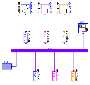
The same is also true for real technical systems. To reduce complexity and get higher flexibility, many technical systems use data buses to exchange data between components. For the same reasons, it is often better to use a "signal bus" concept also in a Modelica model. This is demonstrated at hand of this model (Modelica.Blocks.Examples.BusUsage), see diagram layer:
Difficulties arise if the input or output connector of an input/output block shall be connected directly to a variable of a bus because connections can only be performed between connectors but not between variables. For convenience, single variable connectors for Real, Integer and Boolean variables are provided as Modelica.Blocks.Interfaces.RealPort, Modelica.Blocks.Interfaces.IntegerPort, Modelica.Blocks.Interfaces.BooleanPort. For example, the RealPort connector is basically defined as:
connector RealPort = Real;
This allows a definition of a bus in the form:
   connector Bus
      RealPort r1;
      RealPort r2;
        ...
   end Bus;
and a connection to r1 and r2 is possible since these are connectors. Unfortunately, signals defined in this way have, by default, no unit. To improve this situation, a RealPort is actually defined as
   connector RealPort
      replaceable type SignalType = Real;
      extends SignalType;
   end RealPort;
This allows a redeclaration of the Real type to the desired type, such as:
   connector Bus
      import SI=Modelica.SIunits;
      RealPort v(redeclare SignalType=SI.Velocity);
      RealPort p(redeclare SignalType=SI.Pressure);
      ...
   end Bus;
In order to connect from a RealPort connector to an InPort or OutPort connector of a block from the Modelica.Blocks package, an adaptor block is needed, since the two connectors are not compatible. Appropriate adaptors are provided in Modelica.Blocks.Interfaces.BusAdaptors. The usage can be seen in the diagram layer of the model at hand (Modelica.Blocks.Examples.BusUsage).
If a bus connector contains many signals it is no longer so easy to test just one part of a system, because all parts of the bus connector must get a value. To simplify this, it is practical to provide a RestBus component which sets all parts of a bus to a default value when selected via the parameter menu. This is also demonstrated in the example model (see diagram layer).
Simulate the system for 1 s. The outputs of the 'receive' signal blocks should be the same as the inputs of the 'send' signal blocks.
encapsulated model BusUsage "Demonstration of signal bus usage"
  import Modelica.Icons;
  import Modelica.Blocks.Interfaces.BusAdaptors;
  import Modelica.Blocks.Sources;

  extends Icons.Example;

protected
  Interfaces.Bus bus;
public
  BusAdaptors.SendReal putRealSignal1;
  BusAdaptors.SendBoolean putBooleanSignal;
  BusAdaptors.SendInteger putIntegerSignal;
  BusAdaptors.ReceiveReal getRealSignal1;
  BusAdaptors.ReceiveBoolean getBooleanSignal;
  BusAdaptors.ReceiveInteger getIntegerSignal;
  RestBus restBus(set_realSignal2=true);
  Sources.IntegerStep generateIntegerSignal(
    height={1},
    offset={2},
    startTime={0.5});
  Sources.BooleanStep generateBooleanSignal(startTime={0.5});
  Sources.Sine generateRealSignal1;

  encapsulated package Interfaces
    "Interfaces specialised for this example"

    connector MultiPort "Combined port of real and boolean signal"
      Real myRealSignal;
      Boolean myBooleanSignal;

    end MultiPort;

    connector Bus "Signal bus"
      import SI = Modelica.SIunits;
      import Modelica.Blocks.Interfaces.*;

      RealPort realSignal1(redeclare type SignalType = SI.AngularVelocity) "First Real signal (angular velocity)";
      RealPort realSignal2 "Second Real signal";
      IntegerPort integerSignal "Integer signal";
      BooleanPort booleanSignal "Boolean signal";
      MultiPort multiSignal "Combined signal";

    end Bus;
  end Interfaces;

  encapsulated model Part "Component with MultiPort connector"
    import Modelica.Blocks.Examples;

    Examples.BusUsage.Interfaces.MultiPort multiSignal;

  equation
    multiSignal.myRealSignal = time;
    multiSignal.myBooleanSignal = time > 0.5;
  end Part;

  encapsulated model RestBus
    "Set default values for bus variables that are not defined elsewhere"


    import Modelica.Blocks.Examples;

    parameter Boolean set_realSignal1=false
      "Set dummy value for desiredThrottle";
    parameter Boolean set_realSignal2=false "Set dummy value for brake";
    parameter Boolean set_integerSignal=false
      "Set dummy value for controlLeverPosition";
    parameter Boolean set_booleanSignal=false "Set dummy value for desiredGear"
      ;
    parameter Boolean set_multiSignal=false "Set dummy value for ignition";

    Examples.BusUsage.Interfaces.Bus bus;
  equation
    if set_realSignal1 then
      bus.realSignal1 = 0;
    end if;
    if set_realSignal2 then
      bus.realSignal2 = 0;
    end if;
    if set_integerSignal then
      bus.integerSignal = 0;
    end if;
    if set_booleanSignal then
      bus.booleanSignal = false;
    end if;
    if set_multiSignal then
      bus.multiSignal.myRealSignal = 0;
      bus.multiSignal.myBooleanSignal = false;
    end if;
  end RestBus;

  Part part;
equation

  connect(putRealSignal1.toBus, bus.realSignal1);
  connect(putIntegerSignal.toBus, bus.integerSignal);
  connect(generateRealSignal1.outPort, putRealSignal1.inPort);
  connect(generateBooleanSignal.outPort, putBooleanSignal.inPort);
  connect(generateIntegerSignal.outPort, putIntegerSignal.inPort);
  connect(getRealSignal1.fromBus, bus.realSignal1);
  connect(getIntegerSignal.fromBus, bus.integerSignal);
  connect(restBus.bus, bus);
  connect(putBooleanSignal.toBus, bus.booleanSignal);
  connect(getBooleanSignal.fromBus, bus.booleanSignal);
  connect(part.multiSignal, bus.multiSignal);
end BusUsage;
 Modelica.Blocks.Examples.BusUsage.RestBus

| Name | Default | Description |
|---|---|---|
| set_realSignal1 | false | Set dummy value for desiredThrottle |
| set_realSignal2 | false | Set dummy value for brake |
| set_integerSignal | false | Set dummy value for controlLeverPosition |
| set_booleanSignal | false | Set dummy value for desiredGear |
| set_multiSignal | false | Set dummy value for ignition |
encapsulated model RestBus
  "Set default values for bus variables that are not defined elsewhere"


  import Modelica.Blocks.Examples;

  parameter Boolean set_realSignal1=false "Set dummy value for desiredThrottle"
    ;
  parameter Boolean set_realSignal2=false "Set dummy value for brake";
  parameter Boolean set_integerSignal=false
    "Set dummy value for controlLeverPosition";
  parameter Boolean set_booleanSignal=false "Set dummy value for desiredGear";
  parameter Boolean set_multiSignal=false "Set dummy value for ignition";

  Examples.BusUsage.Interfaces.Bus bus;
equation
  if set_realSignal1 then
    bus.realSignal1 = 0;
  end if;
  if set_realSignal2 then
    bus.realSignal2 = 0;
  end if;
  if set_integerSignal then
    bus.integerSignal = 0;
  end if;
  if set_booleanSignal then
    bus.booleanSignal = false;
  end if;
  if set_multiSignal then
    bus.multiSignal.myRealSignal = 0;
    bus.multiSignal.myBooleanSignal = false;
  end if;
end RestBus;
 Modelica.Blocks.Examples.BusUsage.Part

encapsulated model Part "Component with MultiPort connector"
  import Modelica.Blocks.Examples;

  Examples.BusUsage.Interfaces.MultiPort multiSignal;

equation
  multiSignal.myRealSignal = time;
  multiSignal.myBooleanSignal = time > 0.5;
end Part;