


The network subpackage contains the various network components.
 ObjectStab.Network.Bus

model Bus "Busbar model"
  extends Partials.BusBase;
equation
  T.ia = 0;
  T.ib = 0;
end Bus;
 ObjectStab.Network.FaultedBus
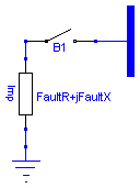
The shunt fault is modelled as an impedance connected to ground through
a breaker. The fault is applied at simulation time FaultTime and stays
active for the duration of FaultDuration.

For numerical reasons, the fault impedance must not be exactly equal
to zero.
| Name | Default | Description |
|---|---|---|
| FaultTime | 10 | Time of fault occurence [s] |
| FaultDuration | 1 | Duration of fault [s] |
| FaultR | 0.1 | Fault Resistance [p.u.] |
| FaultX | 0 | Fault Reactance [p.u.] |
model FaultedBus "Busbar model with shunt fault"
  extends Partials.BusBase;
  parameter Base.Time FaultTime=10 "Time of fault occurence";
  parameter Base.Duration FaultDuration=1 "Duration of fault";
  parameter Base.Resistance FaultR=0.1 "Fault Resistance";
  parameter Base.Reactance FaultX=0 "Fault Reactance";
  Base.CurrentAmplitude iFault "Fault Current";

  ObjectStab.Network.Impedance Imp(R=FaultR, X=FaultX);
  ObjectStab.Network.Ground G;
  ObjectStab.Network.Breaker B1(OpenTime=FaultTime + FaultDuration,
      CloseTime=FaultTime);
equation
  connect(Imp.T1, G.T);
  connect(Imp.T2, B1.T1);
  connect(B1.T2, T);
  iFault = sqrt(G.T.ia*G.T.ia + G.T.ib*G.T.ib);
end FaultedBus;
 ObjectStab.Network.Pilink2

Transmission line modelled in pi-equivalent form according to [1,pp. 44-45]
realized using the detailed phasor equations for the Pi-link. This model is
more computationally efficient than the one realized using connection of the
Impedance and  Admittance models - use this one for large power system models.

For simplicity, the shunt Conductance G has been omitted from the equation,
and for numerical reasons, the R+jX must not be set equal to zero.

---
[1] J. Machowski, J.W. Bialek, and J.R. Bumby, Power System Dynamics
and Stability, Number ISBN 0-471-97174. Wiley, 1993.
| Name | Default | Description |
|---|---|---|
| R | 0.0 | Series Resistance [p.u.] |
| X | 0.1 | Series Reactance [p.u.] |
| B | 0.1 | Shunt Susceptance [p.u.] |
| G | 0.0 | Shunt Conductance [p.u.] |
model Pilink2 "Pilink transmission line model"
  extends Partials.PilinkBase;
equation
  T1.ib = 1/2*(-2*R*T2.vb + 2*R*T1.vb + B*R^2 + B*R^2*T1.va + 2*T2.va*X - 2*T1
    .va*X + B*X^2 + B*X^2*T1.va)/(R^2 + X^2);
  T2.ib = 1/2*(2*R*T2.vb - 2*R*T1.vb + B*R^2 + B*R^2*T2.va - 2*T2.va*X + 2*T1.
    va*X + B*X^2 + B*X^2*T2.va)/(R^2 + X^2);
  T2.ia = -1/2*(-2*R*T2.va + 2*R*T1.va - 2*T2.vb*X + 2*T1.vb*X + B*T2.vb*R^2
     + B*X^2*T2.vb)/(R^2 + X^2);
  T1.ia = -1/2*(2*R*T2.va - 2*R*T1.va + 2*T2.vb*X - 2*T1.vb*X + B*T1.vb*R^2 +
    B*X^2*T1.vb)/(R^2 + X^2);

end Pilink2;
 ObjectStab.Network.FixTransformer

| Name | Default | Description |
|---|---|---|
| R | 0.0 | Leakage Resistance [p.u.] |
| X | 0.1 | Leakage Reactance [p.u.] |
| nn | 1.0 | Fixed Tap Ratio [p.u.] |
model FixTransformer "Fix Transformer"
  extends Partials.ImpTransformer;
  parameter Base.TapRatio nn=1.0 "Fixed Tap Ratio";
equation
  n = nn;
end FixTransformer;
 ObjectStab.Network.TCULDis
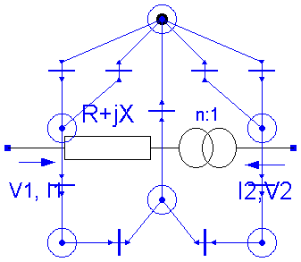
Discrete implementation of Tap-Changing Under Load (TCUL) transformer according to
method D1-D4 using a state-machine implementation of the control system and
tap changer mechanism.
| Name | Default | Description |
|---|---|---|
| R | 0.0 | Leakage Resistance [p.u.] |
| X | 0.1 | Leakage Reactance [p.u.] |
| method | 3 | Method number |
| stepsize | 0.0167 | Step Size [p.u.] |
| mintap | -8 | Minimum tap step [1] |
| maxtap | 8 | Maximum tap step [1] |
| Tm0 | 10 | Mechanical Time Delay [s] |
| Td0 | 20 | Controller Time Delay 1 [s] |
| Td1 | 20 | Controller Time Delay 1 [s] |
| DB | 0.03 | TCUL Voltage Deadband (double-sided) [p.u.] |
| Vref | 1 | TCUL Voltage Reference [p.u.] |
model TCULDis
  "Tap-Changing Under Load (TCUL) transformer with discrete implementation"

  extends Partials.TCULBase;

  Base.Time up_counter(start=-10);
  Base.Time down_counter(start=-10);
  Base.Time Td;
  Base.Time Tm;
  ObjectStab.petri1.StartPlace wait;
  ObjectStab.petri1.Place countup;
  ObjectStab.petri1.Transition Tr1(condLabel="Verr<-DB/2");
  ObjectStab.petri1.Transition Tr2(condLabel="Verr>-DB/2");
  ObjectStab.petri1.Place actionup;
  ObjectStab.petri1.Transition Tr4(condLabel="Timer>Td+Tm");
  ObjectStab.petri1.Place updatetap;
  ObjectStab.petri1.Transition Tr5(condLabel="");
  ObjectStab.petri1.Transition Tr3(condLabel="Timer>Td");
  ObjectStab.petri1.Place countdown;
  ObjectStab.petri1.Transition Tr6(condLabel="Verr>DB/2");
  ObjectStab.petri1.Transition Tr7(condLabel="Verr<DB/2");
  ObjectStab.petri1.Place actiondown;
  ObjectStab.petri1.Transition Tr8(condLabel="Timer>Td+Tm");
  ObjectStab.petri1.Transition Tr9(condLabel="Timer>Td");
equation
  connect(countup.place, Tr1.out);
  connect(Tr1.in_, wait.place);
  connect(Tr2.out, wait.place);
  connect(Tr2.in_, countup.place);
  connect(countup.place, Tr3.in_);
  connect(Tr3.out, actionup.place);
  connect(actionup.place, Tr4.in_);
  connect(Tr4.out, updatetap.place);
  connect(updatetap.place, Tr5.in_);
  connect(Tr5.out, wait.place);
  connect(Tr7.out, wait.place);
  connect(Tr6.in_, wait.place);
  connect(Tr6.out, countdown.place);
  connect(countdown.place, Tr7.in_);
  connect(Tr8.in_, actiondown.place);
  connect(Tr8.out, updatetap.place);
  connect(countdown.place, Tr9.in_);
  connect(Tr9.out, actiondown.place);
  Td = if (method == 1) then Td0 else if (method == 2 or method == 3) then Td0
    *DB/2/abs(udev) else Td1 + Td0*DB/2/abs(udev);
  Tm = if method == 3 then Tm0*DB/2/abs(udev) else Tm0;

  Tr1.condition = (udev < -DB/2) and (tappos < maxtap);
  Tr2.condition = udev > -DB/2;
  Tr3.condition = Time - new(up_counter) > Td;
  Tr4.condition = Time - up_counter > Td + Tm;
  Tr5.condition = not (new(tappos) == tappos);
  Tr6.condition = udev > DB/2 and (tappos > mintap);
  Tr7.condition = udev < DB/2;
  Tr8.condition = Time - down_counter > Td + Tm;
  Tr9.condition = Time - new(down_counter) > Td;

  when countup.state then
    new(up_counter) = Time;
  end when;

  when countdown.state then
    new(down_counter) = Time;
  end when;

  when updatetap.state then
    new(tappos) = if (up_counter > down_counter) then (tappos + 1) else (
      tappos - 1);
  end when;

  n = 1 + tappos*stepsize;
end TCULDis;
 ObjectStab.Network.TCULCon
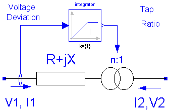
Continuous approximation of Tap-Changing Under Load (TCUL) according to
method C1-C4
| Name | Default | Description |
|---|---|---|
| R | 0.0 | Leakage Resistance [p.u.] |
| X | 0.1 | Leakage Reactance [p.u.] |
| method | 3 | Method number |
| stepsize | 0.0167 | Step Size [p.u.] |
| mintap | -8 | Minimum tap step [1] |
| maxtap | 8 | Maximum tap step [1] |
| Tm0 | 10 | Mechanical Time Delay [s] |
| Td0 | 20 | Controller Time Delay 1 [s] |
| Td1 | 20 | Controller Time Delay 1 [s] |
| DB | 0.03 | TCUL Voltage Deadband (double-sided) [p.u.] |
| Vref | 1 | TCUL Voltage Reference [p.u.] |
model TCULCon
  "Continuous approximation of Tap-Changing Under Load Transformer (TCUL)"


  extends Partials.TCULBase;
  Base.Time Tc;
  constant Boolean DymolaCompatibility=true;
  Modelica.Blocks.Continuous.LimIntegrator integrator(
    k={1},
    outMax={maxtap*stepsize},
    outMin={mintap*stepsize});
equation

  Tc = if (method == 2) then (Td0*DB/2 + Tm0*abs(udev))/stepsize else if (
    method == 3) then (Tm0 + Td0)*DB/2/stepsize else (Td0*DB/2 + (Tm0 + Td1)*
    abs(udev))/stepsize;

  integrator.inPort.signal = -udev/Tc;
  n = 1 + integrator.outPort.signal;
  tappos = (n - 1)/stepsize;

end TCULCon;
 ObjectStab.Network.FaultedPilink
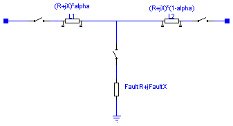
The model of the Pilink with a shunt fault is realized using the Pilink
models and the ideal breaker models.

At time FaultTime, the breaker B3 closes and the ground fault becomes active
for the duration of FaultDuration seconds, after which the line is disconnected
at both ends. The ground fault location is determined by alpha, where alpha=0
corresponds to a fault located at T1 and alpha=1 to a fault location at T2.

For numerical reasons the fault and pilink impedance may not be exactly zero,
and alpha not be equal to 0 or 1.
| Name | Default | Description |
|---|---|---|
| R | 0.0 | Series Resistance [p.u.] |
| X | 0.1 | Series Reactance [p.u.] |
| B | 0.1 | Shunt Susceptance [p.u.] |
| G | 0.0 | Shunt Conductance [p.u.] |
| FaultTime | 1 | Time of fault occurence [s] [s] |
| FaultDuration | 1 | Fault Duration [s] [s] |
| alpha | 0.5 | Position of Fault |
| FaultR | 1e-5 | Fault Resistance [p.u.] |
| FaultX | 1e-5 | Fault Reactance [p.u.] |
model FaultedPilink "Pilink with shunt fault model"
  extends Partials.PilinkBase;
  parameter Base.Time FaultTime=1 "Time of fault occurence [s]";
  parameter Base.Duration FaultDuration=1 "Fault Duration [s]";
  parameter Real alpha=0.5 "Position of Fault";
  parameter Base.Resistance FaultR=1e-5 "Fault Resistance";
  parameter Base.Reactance FaultX=1e-5 "Fault Reactance";

  ObjectStab.Network.Pilink2 L1(
    R=R*alpha,
    X=X*alpha,
    B=B*alpha,
    G=G*alpha);
  ObjectStab.Network.Pilink2 L2(
    R=R*(1 - alpha),
    X=X*(1 - alpha),
    G=G*(1 - alpha),
    B=B*(1 - alpha));
  ObjectStab.Network.Breaker B1(OpenTime=FaultTime + FaultDuration,
      CloseTime=-1e10);
  ObjectStab.Network.Breaker B2(OpenTime=FaultTime + FaultDuration,
      CloseTime=-1e10);
  ObjectStab.Network.Impedance FaultImp(R=FaultR, X=FaultX);
  ObjectStab.Network.Breaker B3(OpenTime=FaultTime + FaultDuration,
      CloseTime=FaultTime);
  ObjectStab.Network.Ground Gr;
equation
  connect(B1.T1, T1);
  connect(B1.T2, L1.T1);
  connect(L2.T2, B2.T1);
  connect(Gr.T, FaultImp.T1);
  connect(FaultImp.T2, B3.T1);
  connect(B2.T2, T2);
  connect(B3.T2, L1.T2);
  connect(L1.T2, L2.T1);
end FaultedPilink;
 ObjectStab.Network.Pilink
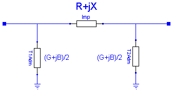
Transmission line modelled in pi-equivalent form according to [1,pp. 44-45]
realized using the Impedance and Admittance submodels.

For numerical reasons, the R+jX must not be set equal to zero.

---
[1] J. Machowski, J.W. Bialek, and J.R. Bumby, Power System Dynamics
and Stability, Number ISBN 0-471-97174. Wiley, 1993.
| Name | Default | Description |
|---|---|---|
| R | 0.0 | Series Resistance [p.u.] |
| X | 0.1 | Series Reactance [p.u.] |
| B | 0.1 | Shunt Susceptance [p.u.] |
| G | 0.0 | Shunt Conductance [p.u.] |
model Pilink "Pilink transmission line model"
  extends Partials.PilinkBase;

  ObjectStab.Network.Impedance Imp(R=R, X=X);
  ObjectStab.Network.Admittance T2Adm(G=G/2, B=B/2);
  ObjectStab.Network.Admittance T1Adm(G=G/2, B=B/2);
  ObjectStab.Network.Ground GT1;
  ObjectStab.Network.Ground GT2;
equation
  connect(T2Adm.T1, GT2.T);
  connect(GT1.T, T1Adm.T1);
  connect(T2, Imp.T2);
  connect(T2Adm.T2, T2);
  connect(T1, Imp.T1);
  connect(T1Adm.T2, T1);
end Pilink;
 ObjectStab.Network.Admittance

The admittance model is governed by the equations:

           G+jB
           ----
V1, I1  ---    --- V2, I2
    ->     ----        <-


I1 = (G+jB) * (V1-V2)
I1 + I2 = 0:
| Name | Default | Description |
|---|---|---|
| G | 0.0 | Conductance [p.u.] |
| B | 0.1 | Susceptance [p.u.] |
model Admittance "Admittance"
  extends Base.TwoPin;

  parameter Base.Conductance G=0.0 "Conductance";
  parameter Base.Susceptance B=0.1 "Susceptance";

equation
  [T1.ia; T1.ib] = [G, -B; B, G]*[T1.va - T2.va; T1.vb - T2.vb];
  T1.ia + T2.ia = 0;
  T1.ib + T2.ib = 0;
end Admittance;
 ObjectStab.Network.Ground

This model can be used to define a ground point, i.e., a point where the voltage is
zero:

V = 0   <=> 1+va = 0, vb = 0

Several (or no) ground points may be used in a power system model.
model Ground "Ground Point"
  extends Base.OnePin;
equation
  1 + T.va = 0;
  T.vb = 0;
end Ground;
 ObjectStab.Network.Impedance

The impedance model is governed by the equations:

           R+jX
           ----
V1, I1  ---    --- V2, I2
    ->     ----        <-


V1 - V2 = (R+jX) * I1
I1 + I2 = 0:


For numerical reasons, R and X may not both be set to zero.
| Name | Default | Description |
|---|---|---|
| R | 0.0 | Resistance [p.u.] |
| X | 0.1 | Reactance [p.u.] |
model Impedance "Impedance model"
  extends Base.TwoPin;

  parameter Base.Resistance R=0.0 "Resistance";
  parameter Base.Reactance X=0.1 "Reactance";

equation
  [T1.ia; T1.ib] = 1/(R*R + X*X)*[R, X; -X, R]*[T1.va - T2.va; T1.vb - T2.vb];
  T1.ia + T2.ia = 0;
  T1.ib + T2.ib = 0;
end Impedance;
 ObjectStab.Network.OpenedPilink

Breakers B1 and B2 opens simultaneously at simulation time OpenTime, and stays
open for the duration of OpenDuration, after which they are simultanously closed.
| Name | Default | Description |
|---|---|---|
| R | 0.0 | Series Resistance [p.u.] |
| X | 0.1 | Series Reactance [p.u.] |
| B | 0.1 | Shunt Susceptance [p.u.] |
| G | 0.0 | Shunt Conductance [p.u.] |
| OpenTime | 10 | Time of branch opening [s] [s] |
| OpenDuration | 1e10 | Duration of the branch opening [s] [s] |
model OpenedPilink "Pilink model with breakers"
  extends Partials.PilinkBase;

  parameter Base.Time OpenTime=10 "Time of branch opening [s]";
  parameter Base.Duration OpenDuration=1e10
    "Duration of the branch opening [s]";

  ObjectStab.Network.Pilink Pi(
    R=R,
    X=X,
    B=B,
    G=G);
  ObjectStab.Network.Breaker B1(OpenTime=OpenTime, CloseTime=OpenDuration);
  ObjectStab.Network.Breaker B2(OpenTime=OpenTime, CloseTime=OpenDuration);
equation
  connect(B1.T1, T1);
  connect(B1.T2, Pi.T2);
  connect(B2.T1, Pi.T1);
  connect(B2.T2, T2);
end OpenedPilink;
 ObjectStab.Network.Breaker

The ideal breaker model is governed by the following models:


if breaker is closed then
  V1 = V2
  I1 + I2 = 0

else
  I1 = 0
  I2 = 0
| Name | Default | Description |
|---|---|---|
| OpenTime | 1 | Opening time [s] |
| CloseTime | 1e10 | Closing time [s] |
model Breaker "Ideal Breaker model"
  extends Base.TwoPin;
  parameter Base.Time OpenTime=1 "Opening time";
  parameter Base.Time CloseTime=1e10 "Closing time";

  Boolean closed(start=OpenTime < CloseTime);

equation
  closed = (OpenTime > CloseTime) and (time > CloseTime and time <
    OpenTime) or (OpenTime < CloseTime) and (time < OpenTime or time
     > CloseTime);

  0 = if closed then (T1.va - T2.va) else T1.ia;
  0 = if closed then (T1.vb - T2.vb) else T1.ib;

  T1.ia + T2.ia = 0;
  T1.ib + T2.ib = 0;
end Breaker;
 ObjectStab.Network.SeriesFault

The series fault is realized using the ideal breaker model.
The fault becomes active (non-conductive) at time FaultTime
and stays non-conductive for the duration of FaultDuration seconds,
after which the fault is cleared.
| Name | Default | Description |
|---|---|---|
| FaultTime | 1 | Opening time [s] |
| FaultDuration | 1 | Duration of Fault [s] |
model SeriesFault "Series Fault model"
  extends Base.TwoPin;
  parameter Base.Time FaultTime=1 "Opening time";
  parameter Base.Duration FaultDuration=1 "Duration of Fault";

  ObjectStab.Network.Breaker B1(OpenTime=FaultTime, CloseTime=FaultTime +
        FaultDuration);
equation
  connect(T1, B1.T1);
  connect(B1.T2, T2);
end SeriesFault;