


This package contains ideal components:
Modelica.Electrical.Analog.Ideal.IdealThyristor
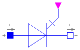
Ideal thyristor ... < description will be added >
| Name | Default | Description |
|---|---|---|
| Roff | 1.E-5 | Closed thyristor resistance [Ohm] |
| Gon | 1.E-5 | Opened thyristor conductance [S] |
model IdealThyristor "Ideal thyristor"
  extends Modelica.Electrical.Analog.Interfaces.OnePort;
  parameter SIunits.Resistance Roff(final min=0) = 1.E-5
    "Closed thyristor resistance";
  parameter SIunits.Conductance Gon(final min=0) = 1.E-5
    "Opened thyristor conductance";
protected
  Real s "Auxiliary variable";
  Boolean off(start=true);
  Boolean fire(start=true);
public
  Modelica.Blocks.Interfaces.BooleanInPort firePort(final n=1);
equation
  fire = firePort.signal[1];
  off = s < 0 or pre(off) and not fire;
  v = s*(if off then 1 else Roff);
  i = s*(if off then Gon else 1);
end IdealThyristor;
Modelica.Electrical.Analog.Ideal.IdealGTOThyristor

Ideal GTO thyristor ...
| Name | Default | Description |
|---|---|---|
| Roff | 1.E-5 | Closed thyristor resistance [Ohm] |
| Gon | 1.E-5 | Opened thyristor conductance [S] |
model IdealGTOThyristor "Ideal GTO thyristor"
  extends Modelica.Electrical.Analog.Interfaces.OnePort;
  parameter SIunits.Resistance Roff(final min=0) = 1.E-5
    "Closed thyristor resistance";
  parameter SIunits.Conductance Gon(final min=0) = 1.E-5
    "Opened thyristor conductance";
protected
  Real s "Auxiliary variable";
  Boolean off(start=true) "Position of switch";
  Boolean fire;
public
  Modelica.Blocks.Interfaces.BooleanInPort firePort(final n=1);
equation
  fire = firePort.signal[1];
  off = s < 0 or not fire;
  v = s*(if off then 1 else Roff);
  i = s*(if off then Gon else 1);
end IdealGTOThyristor;
Modelica.Electrical.Analog.Ideal.IdealSwitch
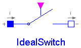
Ideal electrical switch. In order to prevent singularities during switching, the opened switch has a high resistance and the closed switch has a low resistance.
If the actual circuit has an appropriate structure, the limiting case is also allowed, i.e., the resistance of the closed switch could be exactly zero and the conductance of the open switch could be also exactly zero (i.e. the resistance is infinity). Note, there are circuits, where a description with zero/infinity resistances is not possible.
| Name | Default | Description |
|---|---|---|
| Roff | 1.E-5 | Closed switch resistance [Ohm] |
| Gon | 1.E-5 | Opened switch conductance [S] |
model IdealSwitch "Ideal electrical switch"
  extends Modelica.Electrical.Analog.Interfaces.OnePort;
  parameter SIunits.Resistance Roff(final min=0) = 1.E-5
    "Closed switch resistance";
  parameter SIunits.Conductance Gon(final min=0) = 1.E-5
    "Opened switch conductance";
protected
  Real s "Auxiliary variable";
  Boolean off;
public
  Modelica.Blocks.Interfaces.BooleanInPort control(final n=1, signal(start=
          {false})) "true/false opened/closed switch";
equation
  off = control.signal[1];
  v = s*(if off then 1 else Roff);
  i = s*(if off then Gon else 1);
end IdealSwitch;
Modelica.Electrical.Analog.Ideal.ControlledIdealSwitch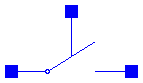
The ideal switch is a three-pole. If the third pin voltage exceeds the given parameter Voltage, the pins p and n are open (no current flowing, any voltage possible). Otherwise, p and n are short cut.
| Name | Default | Description |
|---|---|---|
| level | Switch level [V] | |
| Roff | 1.E-5 | Closed switch resistance [Ohm] |
| Gon | 1.E-5 | Opened switch conductance [S] |
model ControlledIdealSwitch
  parameter SIunits.Voltage level "Switch level";
  parameter SIunits.Resistance Roff(final min=0) = 1.E-5
    "Closed switch resistance";
  parameter SIunits.Conductance Gon(final min=0) = 1.E-5
    "Opened switch conductance";
protected
  Real s "Auxiliary variable";
public
  Modelica.Electrical.Analog.Interfaces.Pin p "Positive pin";
  Modelica.Electrical.Analog.Interfaces.Pin n "Negative pin";
  Modelica.Electrical.Analog.Interfaces.Pin control
    "Control pin: control.v > level open, otherwise closed";
equation
  control.i = 0;
  0 = p.i + n.i;
  p.v - n.v = s*(if (control.v < level) then Roff else 1);
  n.i = s*(if (control.v < level) then 1 else Gon);
end ControlledIdealSwitch;
Modelica.Electrical.Analog.Ideal.ControlledIdealCommutingSwitch
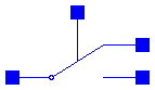
The commuting switch is a four pole. The switching behaviour is controlled by the fourth pin. If its voltage exceeds the parameter Voltage value, the first pin p is chort cut to the second pin ng. Otherwise, the pin p is short cut to the third pin n1.
| Name | Default | Description |
|---|---|---|
| level | Switch level [V] | |
| Roff | 1.E-5 | Closed switch resistance [Ohm] |
| Gon | 1.E-5 | Opened switch conductance [S] |
model ControlledIdealCommutingSwitch "Ideal commuting switch"
  parameter SIunits.Voltage level "Switch level";
  parameter SIunits.Resistance Roff(final min=0) = 1.E-5
    "Closed switch resistance";
  parameter SIunits.Conductance Gon(final min=0) = 1.E-5
    "Opened switch conductance";
public
  Modelica.Electrical.Analog.Interfaces.Pin p "Positive pin";
  Modelica.Electrical.Analog.Interfaces.Pin n2 "Negative pin 2";
  Modelica.Electrical.Analog.Interfaces.Pin n1 "Negative pin 1";
  Modelica.Electrical.Analog.Interfaces.Pin control
    "Control pin: control.v > level p--n2, otherwise p--n1";
protected
  Real s1;
  Real s2 "Auxiliary variables";
equation
  control.i = 0;
  0 = p.i + n2.i + n1.i;

  p.v - n1.v = s1*(if (control.v > level) then 1 else Roff);
  n1.i = s1*(if (control.v > level) then Gon else 1);
  p.v - n2.v = s2*(if (control.v > level) then Roff else 1);
  n2.i = s2*(if (control.v > level) then 1 else Gon);
end ControlledIdealCommutingSwitch;
Modelica.Electrical.Analog.Ideal.IdealOpAmp
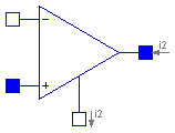
The ideal OpAmp is a two-port. The left port is fixed to v1=0 and i1=0 (nullator). At the right port both any voltage v2 and any current i2 are possible (norator).
model IdealOpAmp "Ideal opamp (norator-nullator pair)"
  SIunits.Voltage v1 "Voltage drop over the left port";
  SIunits.Voltage v2 "Voltage drop over the right port";
  SIunits.Current i1
    "Current flowing from pos. to neg. pin of the left port";
  SIunits.Current i2
    "Current flowing from pos. to neg. pin of the right port";
  Modelica.Electrical.Analog.Interfaces.PositivePin p1
    "Positive pin of the left port";
  Modelica.Electrical.Analog.Interfaces.NegativePin n1
    "Negative pin of the left port";
  Modelica.Electrical.Analog.Interfaces.PositivePin p2
    "Positive pin of the right port";
  Modelica.Electrical.Analog.Interfaces.NegativePin n2
    "Negative pin of the right port";
equation
  v1 = p1.v - n1.v;
  v2 = p2.v - n2.v;
  0 = p1.i + n1.i;
  0 = p2.i + n2.i;
  i1 = p1.i;
  i2 = p2.i;
  v1 = 0;
  i1 = 0;
end IdealOpAmp;
Modelica.Electrical.Analog.Ideal.IdealDiode
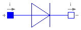
Ideal electrical diode. This is an ideal switch which is open, when it is reversed biased (voltage drop < 0) and which is closed, when it is conducting (current > 0). In order to prevent singularities during switching, the opened diode has a high resistance and the closed diode has a low resistance.
If the actual circuit has an appropriate structure, the limiting case is also allowed, i.e., the resistance of the closed diode could be exactly zero and the conductance of the open diode could be also exactly zero (i.e. the resistance is infinity). Note, there are circuits, where a description with zero/infinity resistances is not possible.
| Name | Default | Description |
|---|---|---|
| Roff | 1.E-5 | Closed diode resistance [Ohm] |
| Gon | 1.E-5 | Opened diode conductance [S] |
model IdealDiode "Ideal electrical diode"
  extends Modelica.Electrical.Analog.Interfaces.OnePort;
  parameter SIunits.Resistance Roff(final min=0) = 1.E-5
    "Closed diode resistance";
  parameter SIunits.Conductance Gon(final min=0) = 1.E-5
    "Opened diode conductance";
  Boolean off(start=true) "Switching state of diode";
protected
  Real s "Auxiliary variable";
equation
  off = s < 0;
  v = s*(if off then 1 else Roff);
  i = s*(if off then Gon else 1);
end IdealDiode;
Modelica.Electrical.Analog.Ideal.IdealTransformer
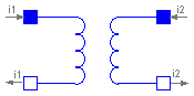
The ideal transformer is an ideal two-port resistive circuit element which is characterized by the following two equations:
    v1 =  n * v2
    i2 = -n * i1
where n is a real number called the turns ratio.
| Name | Default | Description |
|---|---|---|
| n | 1 | Turns ratio |
model IdealTransformer "Ideal electrical transformer"
  extends Modelica.Electrical.Analog.Interfaces.TwoPort;
  parameter Real n=1 "Turns ratio";
equation
  v1 = n*v2;
  i2 = -n*i1;
end IdealTransformer;
Modelica.Electrical.Analog.Ideal.IdealGyrator
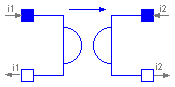
A gyrator is an ideal two-port element defined by the following equations:
    i1 =  G * v2
    i2 = -G * v1
where the constant G is called the gyration conductance.
| Name | Default | Description |
|---|---|---|
| G | 1 | Gyration conductance [S] |
model IdealGyrator "Ideal gyrator"
  extends Modelica.Electrical.Analog.Interfaces.TwoPort;
  parameter SIunits.Conductance G=1 "Gyration conductance";
equation
  i1 = G*v2;
  i2 = -G*v1;
end IdealGyrator;
Modelica.Electrical.Analog.Ideal.Idle
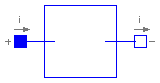
The model Idle is a simple idle running branch.
model Idle "Idle branch"
  extends Modelica.Electrical.Analog.Interfaces.OnePort;
equation

  i = 0;

end Idle;
Modelica.Electrical.Analog.Ideal.Short
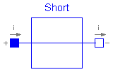
The model Short is a simple short cut branch.
model Short "Short cut branch"
  extends Modelica.Electrical.Analog.Interfaces.OnePort;
equation
  v = 0;
end Short;