


This package contains basic analog electrical components:
Modelica.Electrical.Analog.Basic.Ground

Ground of an electrical circuit. The potential at the ground node is zero. Every electrical circuit has to contain at least one ground object.
model Ground "Ground node"
  Modelica.Electrical.Analog.Interfaces.Pin p;
equation
  p.v = 0;
end Ground;
Modelica.Electrical.Analog.Basic.Resistor
The linear resistor connects the branch voltage v with the branch current i by i*R = v. The Resistance R is allowed to be positive, zero, or negative.
| Name | Default | Description |
|---|---|---|
| R | 1 | Resistance [Ohm] |
model Resistor "Ideal linear electrical resistor"
  extends Modelica.Electrical.Analog.Interfaces.OnePort;
  parameter SIunits.Resistance R=1 "Resistance";
equation
  R*i = v;
end Resistor;
Modelica.Electrical.Analog.Basic.Conductor
The linear conductor connects the branch voltage v with the branch current i by i = v*G. The Conductance G is allowed to be positive, zero, or negative.
| Name | Default | Description |
|---|---|---|
| G | 1 | Conductance [S] |
model Conductor "Ideal linear electrical conductor"
  extends Modelica.Electrical.Analog.Interfaces.OnePort;
  parameter SIunits.Conductance G=1 "Conductance";
equation
  i = G*v;
end Conductor;
Modelica.Electrical.Analog.Basic.Capacitor
The linear capacitor connects the branch voltage v with the branch current i by i = C * dv/dt. The Capacitance C is allowed to be positive, zero, or negative.
| Name | Default | Description |
|---|---|---|
| C | 1 | Capacitance [F] |
model Capacitor "Ideal linear electrical capacitor"
  extends Modelica.Electrical.Analog.Interfaces.OnePort;
  parameter SIunits.Capacitance C=1 "Capacitance";
equation
  i = C*der(v);
end Capacitor;
Modelica.Electrical.Analog.Basic.Inductor
The linear inductor connects the branch voltage v with the branch current i by v = L * di/dt. The Inductance L is allowed to be positive, zero, or negative.
| Name | Default | Description |
|---|---|---|
| L | 1 | Inductance [H] |
model Inductor "Ideal linear electrical inductor"
  extends Modelica.Electrical.Analog.Interfaces.OnePort;
  parameter SIunits.Inductance L=1 "Inductance";
equation
  L*der(i) = v;
end Inductor;
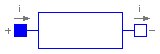
Modelica.Electrical.Analog.Basic.Transformer
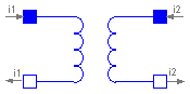
The transformer is a two port. The left port voltage v1, left port current i1, right port voltage v2 and right port current i2 are connected by the following relation:
         / v1 \          / L1   M  \  / i1' \
         |    |    =     |         |  |     |
         \ v2 /          \ M    L2 /  \ i2' /
L1, L2, and M are the primary, secondary, and coupling inductances resp..
| Name | Default | Description |
|---|---|---|
| L1 | 1 | Primary inductance [H] |
| L2 | 1 | Secondary inductance [H] |
| M | 1 | Coupling inductance [H] |
model Transformer "Transformer with two ports"
  extends Modelica.Electrical.Analog.Interfaces.TwoPort;
  parameter SIunits.Inductance L1=1 "Primary inductance";
  parameter SIunits.Inductance L2=1 "Secondary inductance";
  parameter SIunits.Inductance M=1 "Coupling inductance";
equation
  v1 = L1*der(i1) + M*der(i2);
  v2 = M*der(i1) + L2*der(i2);
end Transformer;
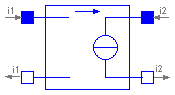
Modelica.Electrical.Analog.Basic.Gyrator
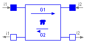
A gyrator is a two-port element defined by the following equations:
    i1 =  G2 * v2
    i2 = -G1 * v1
where the constants G1, G2 are called the gyration conductance.
| Name | Default | Description |
|---|---|---|
| G1 | 1 | Gyration conductance [S] |
| G2 | 1 | Gyration conductance [S] |
model Gyrator "Gyrator"
  extends Modelica.Electrical.Analog.Interfaces.TwoPort;
  parameter SIunits.Conductance G1=1 "Gyration conductance";
  parameter SIunits.Conductance G2=1 "Gyration conductance";
equation
  i1 = G2*v2;
  i2 = -G1*v1;
end Gyrator;
Modelica.Electrical.Analog.Basic.EMF
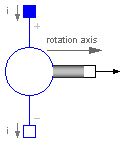
Transforms electrical energy into rotational mechanical energy. Is used as basic building block of an electrical motor. The mechanical connector flange_b can be connected to elements of the Modelica.Mechanics.Rotational library.
| Name | Default | Description |
|---|---|---|
| k | 1 | Transformation coefficient [N.m/A] |
model EMF "Electromotoric force (electric/mechanic transformer)"
  parameter Real k(final unit="N.m/A") = 1
    "Transformation coefficient";

  SIunits.Voltage v "Voltage drop between the two pins";
  SIunits.Current i "Current flowing from positive to negative pin";
  SIunits.AngularVelocity w "Angular velocity of flange_b";
  Modelica.Electrical.Analog.Interfaces.PositivePin p;
  Modelica.Electrical.Analog.Interfaces.NegativePin n;
  Modelica.Mechanics.Rotational.Interfaces.Flange_b flange_b;
equation
  v = p.v - n.v;
  0 = p.i + n.i;
  i = p.i;

  w = der(flange_b.phi);
  k*w = v;
  flange_b.tau = -k*i;
end EMF;
Modelica.Electrical.Analog.Basic.VCV
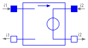
Linear voltage-controlled voltage source

  The linear voltage-controlled voltage source is a TwoPort.
  The right port voltage vr is controlled by the left port voltage vl
  via      v2 = v1 * gain.
  The left port current is zero. Any voltage gain can be chosen.
| Name | Default | Description |
|---|---|---|
| gain | 1 | Voltage gain |
model VCV "Linear voltage-controlled voltage source"
  extends Modelica.Electrical.Analog.Interfaces.TwoPort;
  parameter Real gain=1 "Voltage gain";
equation
  connect(p2, n2);
  v2 = v1*gain;
  i1 = 0;
end VCV;
Modelica.Electrical.Analog.Basic.VCC
Linear voltage-controlled current source

  The linear voltage-controlled current source is a TwoPort.
  The right port current ir is controlled by the left port voltage vl
  via      i2 = v1 * transConductance.
  The left port current is zero. Any transConductance can be chosen.
| Name | Default | Description |
|---|---|---|
| transConductance | 1 | Transconductance [S] |
model VCC "Linear voltage-controlled current source"
  extends Modelica.Electrical.Analog.Interfaces.TwoPort;
  parameter Modelica.SIunits.Conductance transConductance=1
    "Transconductance";
equation
  i2 = v1*transConductance;
  i1 = 0;
end VCC;
Modelica.Electrical.Analog.Basic.CCV
Linear current-controlled voltage source

  The linear current-controlled voltage source is a TwoPort.
  The right port voltage vr is controlled by the left port current i1
  via      v2 = i1 * transResistance.
  The left port voltage is zero. Any transResistance can be chosen.
| Name | Default | Description |
|---|---|---|
| transResistance | 1 | Transresistance [Ohm] |
model CCV "Linear current-controlled voltage source"
  extends Modelica.Electrical.Analog.Interfaces.TwoPort;

  parameter Modelica.SIunits.Resistance transResistance=1
    "Transresistance";
equation
  connect(p2, n2);
  connect(p1, n1);
  v2 = i1*transResistance;
  v1 = 0;
end CCV;
Modelica.Electrical.Analog.Basic.CCC
Linear current-controlled current source

  The linear current-controlled current source is a TwoPort.
  The right port current ir is controlled by the left port current il
  via      ir = il * gain.
  The left port voltage is zero. Any current gain can be chosen.
| Name | Default | Description |
|---|---|---|
| gain | 1 | Current gain |
model CCC "Linear current-controlled current source"
  extends Modelica.Electrical.Analog.Interfaces.TwoPort;
  parameter Real gain=1 "Current gain";
equation
  connect(p1, n1);
  i2 = i1*gain;
  v1 = 0;
end CCC;