This paper describes the 5dpo-2000 team. The paper will be divided into three main sections, corresponding to three main blocks: the Global Level, the Local Level and the Interface Level. These Levels, their subsystems and some implementation details will be described next.
1 Introduction
This is our first participation in the Robocup Competition in the F-2000 League. We have already played in the F-180 League and we tried to incorporate our experience in the design of this team. We think the first and most important issue to be dealt with is the sensorial problem. Without knowing their position and the ball position, the robots are not able to deploy any kind of coherent action. So we are trying to tackle the problem of extracting this information from multiple cameras and other sensors. All the information is acquired by each robot and so we have distributed system. The data must be fused, taking in account their reliability and the communication influence: bandwidth, delays and possible interference.
Each robot has a video acquisition system and a radio link to communicate with the other robots and with the coach. In addition to the video there are other sensors like, infrared and acoustic range finders, contact sensors, etc.
As the radio link cannot be completely reliable we tried to fit the robots with some autonomy so that they can survive a small starvation of orders from the Coach. That can ease the problem of lost packets over the air.
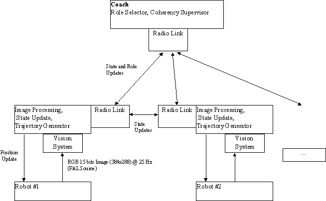
The whole team can be seen as a system divided in two basic levels.
Fig. 1. Robots and Coach and the information flowing between them.
We will now describe the team and its subsystems.
2 The Coach
This is the global Control Level. The global state of the system is updated based on the information flowing from the robots. Data fusion is attempted and adversary robot moves are tracked. A rule based engine is used to classify opponents intents. By observing the present system state as well as a global mid-term strategy, new roles are assigned and sent to the players.
This level closes the global loop but there is some intrinsic lag that degrades its optimal performance. Each robot acquires the image, then some time is lost processing it and more time is lost to transmit the data to the coach. There, the reasoning unit must decide the new course of action and it is necessary to wait for the next time slot to send information to the robots. That is why the local loop, running in each robot, can show a much better performance in some tasks than the globally closed loop.
Other role of the coach is to maintain a "official" global state that can be used to ensure the coherency of the global system state viewed by each robot.
3 The Communications
The information flowing is used by all the robots to update their view of the global state. In that way we can have each robot gaining extra information from the other robots’ sensors.
3.1 The Radio Link
The radio link allows sending and receiving short packets that carry messages from the Coach to the robots and between robots. We have the radio channel time slotted synchronously with a global clock. This global clock is kept by each robot using the time of arrival of the radio signals to compensate any possible drift.
3.2 The Alternative Link
The quality of the communication system is paramount to the team performance. So we are considering adding an alternative communication link, probably an infrared link, to improve the reliability of the overall communication system.
4 The Robots
A robot is an autonomous unit considering a short time frame. The robots are capable of generating a queue of tasks to be performed. These tasks may include following a specified trajectory, holding the ball, passing it along to another team member or maybe shooting for goal. The local control system tries to enforce those orders in the predefined sequence.
Some team tactics are maintained at all times like some defense mechanisms that are enforced during the match. In any case, the defense robots stand in alignment in such a way that the robot that holds the ball can’t easily shoot for goal. This implies the presence of a path planner present in each robot.
Next we describe the basic mechanical and electrical design of the robots.
The robots are fitted with two differential wheels. The wheels are driven independently by separated stepper motors. Two extra free wheels ensure the static stability.
The robots are presently powered by embedded Lead-Acid batteries. The motors are driven by two H-bridges that are directly powered from the batteries. The on board controller is a 8-bit RISC microcontroller (Atmel AVR90S4414). A PC deals with the higher level functions.
Two small single frequency RF modules (433 MHz and 418MHz) are used to communicate with the coach and other robots. Only one can be used at a time.
The PC code was done in C++ in DOS with a 32 bits extender. That was the only way to ensure the hard real-time nature of the tasks. Other operating systems could not guarantee hard real-time behavior.
Our team uses a local vision system as a primary sensorial source for each member. This is our positioning system for the robots, for the opponent robots and for the ball.
This system consists in one or more color video cameras, placed on the robot. The TV signal from these cameras is feed to a video acquisition board placed in the local PC. This board is capable of placing a digitalization of each image frame in the PC memory without CPU intervention, thus wasting almost no processor time. In the end of this process the board can signal the processor the conclusion of that task.
As we are using PAL cameras the image frequency is 50 Hz with alternating even and odd frames. We are only using even frames therefore we have an image update frequency of 25 Hz. Based on the acquired image we try to identify the ball position and also the robots’ position and orientation.
5 Future Work
A disclaimer must be made at this point: between now and the competition there is yet a lot of time to make changes in the described setup. As we test the performance of each subsystem and find better alternatives we will try to implement them. We want the overall system to show a more robust and efficient operation. There is the possibility of adding some kind kicking device to some of our robots.
6 Conclusions
In this paper we described the 5dpo-2000 team and the solutions we found to this problem. Recognizing the overall system state (the ball position and speed, our team’s robots’ state and the adversarial robots’ state) using vision in distributed environment is still a very difficult task. And the quality of the team behavior is very dependent from the accuracy of that system.
The decision of what to do, even with accurate knowledge of the system status, it is a major task on its own. The range of options, some discrete and some continuous has many dimensions and cannot be easily searched. A lot of heuristic rules must be used to trim the possibilities and the best framework to represent and find them is a matter that requires still a lot of research.
[1] Arthur Gelb, Joseph Kasper Jr.,Raymond Nash Jr., Charles Price, Arthur Sutherland Jr.: Applied Optimal Estimation, The M.I.T. Press, (1989)
[2] J. Borenstein, H. R. Everett, L. Feng, S. W. Lee and R. H. Byrne: Where am I? Sensors and Methods for Mobile Robot Positioning, (1996)
[3] J. Carvalho: Dynamic Systems and Automatic Control, Prentice-Hall, (1993)
[4] Huibert Kwakernaak, Raphael Sivan: Linear Optimal Control Systems, Willey-Interscience, (1972)
[5] Jean-Claude Latombe: Robot Motion Planning, Kluwer Academic Publishers, (1991)
[6] Lenart Ljung: System Identification: Theory For The User, Prentice-Hall, (1987)